


–
12
–
English
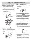
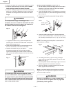
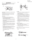
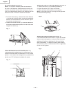
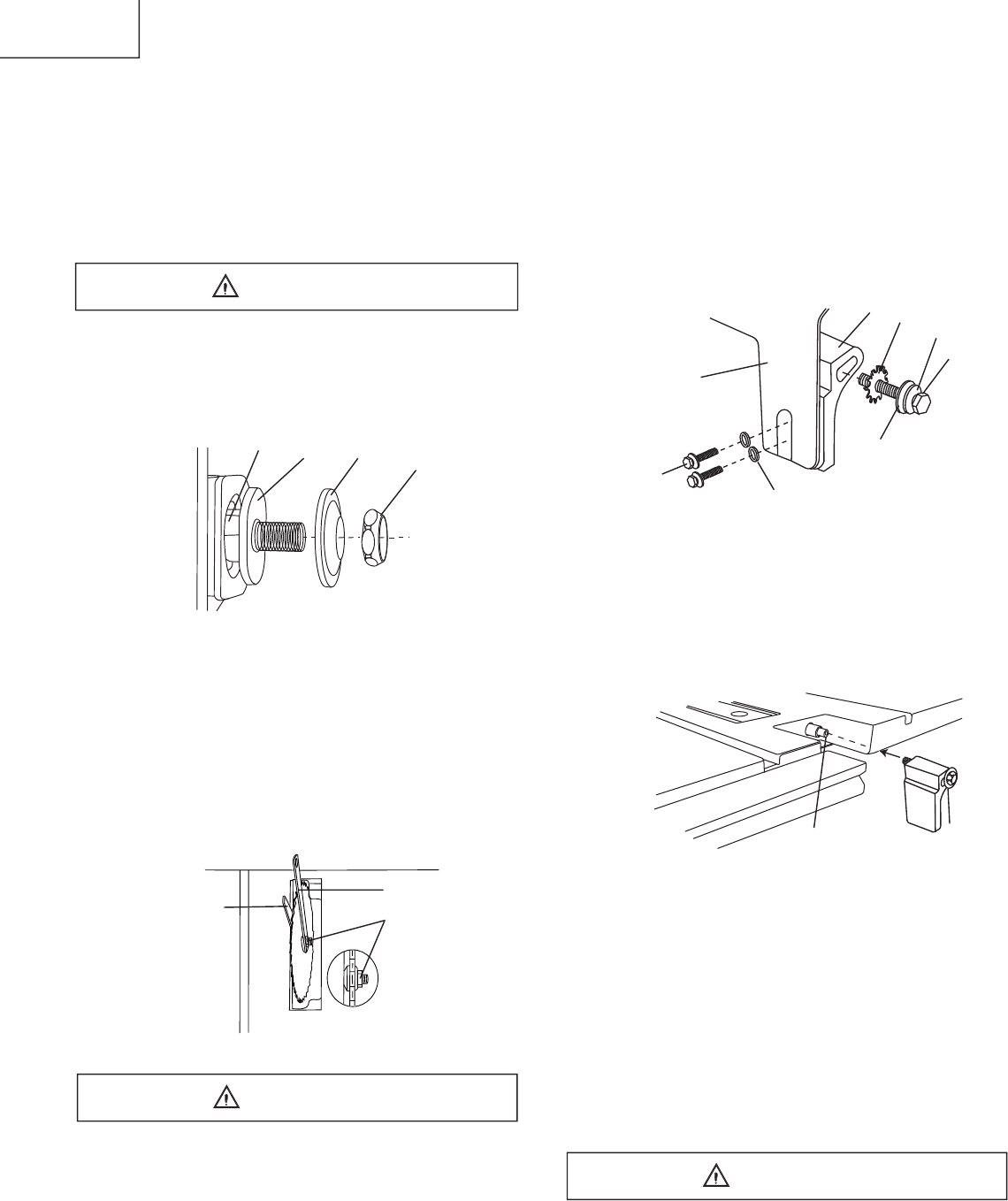
BLADE GUARD ASSEMBLY (FIG. G, H, I )
1. Set the blade to maximum height and the tilt to zero
degrees on the bevel scale with the hand wheels.
Lock the blade bevel lock knob.
2. Place the spring washer (2), fl at washer (3), external
tooth lock washer (4) onto the blade guard mounting
bolt (1-Fig. G).
3. Insert bolt and washer assembly through splitter
bracket (5).
Fig.
G
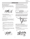
4. Install the blade guard splitter & bracket assembly
into the rear of the saw table. Thread the bolt (1) into
the internally threaded pivot rod (7-Fig. H) until snug.
NOTE:
The blade guard and splitter is removed from
the illustration for clarity.
Fig.
H
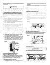
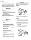
6. Lift blade guard arm (8) up and using a straight
edge, align the blade guard splitter (9) with the saw
blade (10). (Fig. I)
7. Shift the splitter bracket assembly to right or left until
parallel alignment to the blade is achieved.
8. When the splitter is properly aligned with the saw
blade, tighten the bolt securely.
NOTE:
The splitter bracket must always be correctly
aligned so the cut workpiece will pass on either side
without binding or twisting.
See Fig. G fl at washers (11) must be under
bol
ts
(12). NOTE: Be sure to tighten nuts very tight and
periodically check tightness.
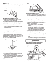
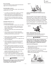
4.
Remove the arbor nut (5) and outer fl ang
e
(6). (Fig. E)
5. Install the saw blade onto the arbor with the
blade
teeth pointing toward the front of the saw
.
6. Install the fl ange (6) against the blade and thread the
arbor nut (5) as far as possible by hand. Ensure that
the blade is fl ush againstthe inner side of the blade
fl ange.
To avoid possible injury and damage to the
workpiece, be sure to install the blade with the teeth
pointing toward the front of table in the direction of
the rotation arrow on the blade guard.
Fig. E
7. To tighten the arbor nut (5), place the open-end
wrench (8) on the fl ats of the saw arbor to keep the
arbor from turning. (Fig. F)
8. Place the box-end wrench (9) on the arbor nut (5),
and turn clockwise (to the rear of the table).
9. R
eplace the blade insert in the table re
cess
, in
sert
the scr
ews thr
ough the
front and rear
hole and
tighten remembering the rubber washer under the
rear of the insert and leveling the rear of the insert to
the table.
Fig. F
To avoid injury from a thrown workpiece, blade
parts, or blade contact, never operate saw without
the proper insert in place. Use the original installed
insert for all throught sawing
operations
except
dado
cut
s.
A special dado inser
t p
late must be install
ed
when using a dado bla
de.
WARNING
4
7
6
5
9
5
8
WARNING
4
Blade guard
splitter
11
12
5
3
2
1
WARNING
7