


–
17
–
English
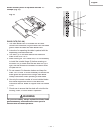
BASIC SAW OPERATIONS
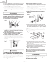
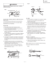
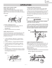
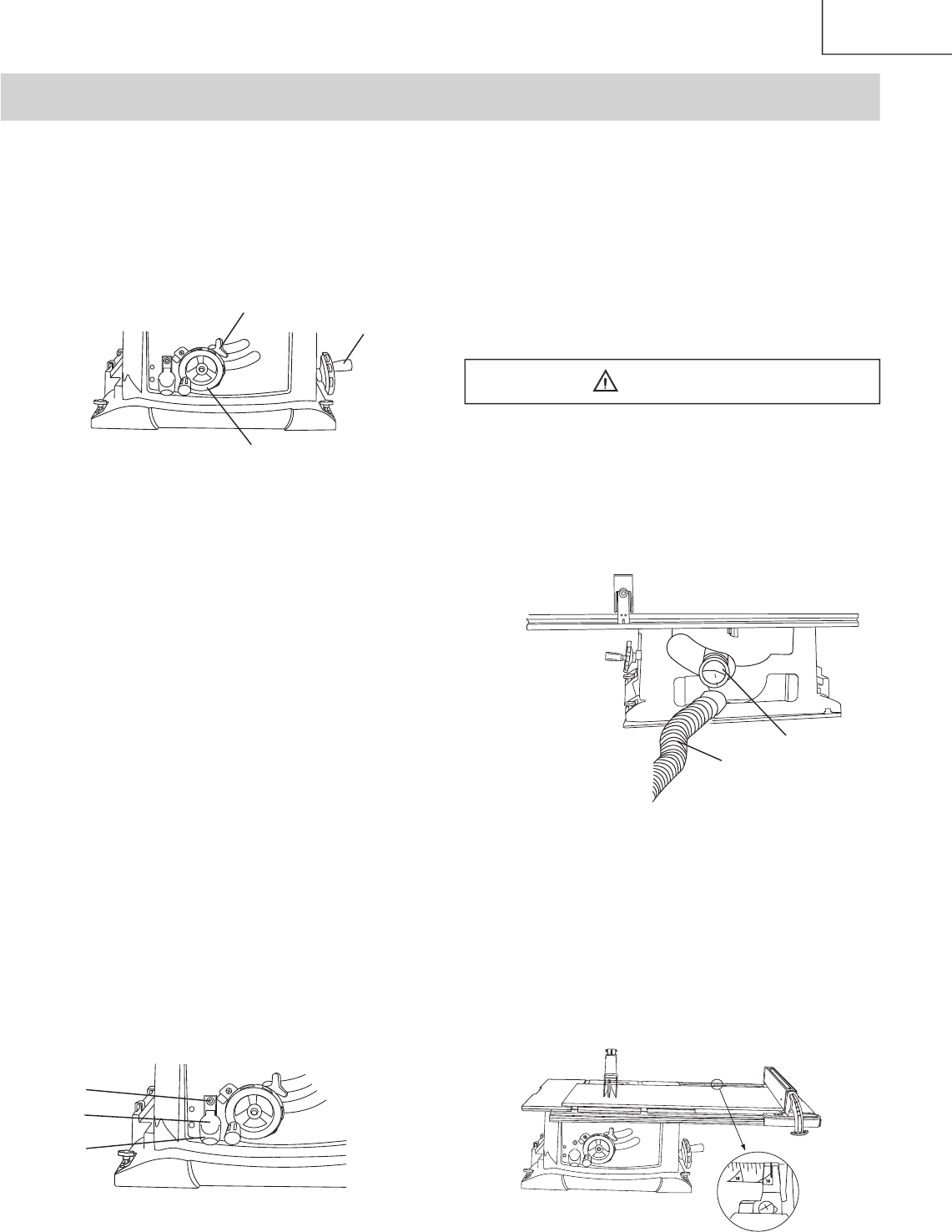
RAISE THE BLADE (FIG. W)
To raise or lower the blade, turn the blade elevation
handwheel (1) to the desired blade height, and then
tighten the bevel lock handle (2) to maintain the desired
blade angle.
Fig.
W
TILTING THE BLADE (FIG. W)
1. To tilt the saw blade for bevel cutting, loosen the
bevel lock knob (2) and turn the tilting
handwheel (3).
2. Tighten the bevel lock knob (2) to secure.
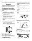
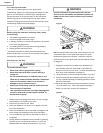
ON/OFF SWITCH (FIG. X)
The ON / OFF switch has a removable safety key. With
the key removed from the switch, unauthorized and
hazardous use by children and others is minimized and
the saw will not turn on.
1. To turn the saw ON, insert key (1) into the slot in
the switch (2). Move the switch upward to the ON
position.
2. To turn the saw OFF, move the switch downward.
3. To lock the switch in the OFF position, grasp the
sides (or yellow part) of the switch toggle (1), and
pull it out.
4. With the switch key removed, the switch will not
operate.
5. If the switch key is removed while the saw is running,
it can be turned OFF but cannot be restarted without
re-inserting the switch key (1).
Fig.
X
OPERATION
OVERLOAD PROTECTION (FIG. X)
This saw has an overload relay button (3) that resets
the motor after it shuts off due to overloading or low
voltage. If the motor stops during operation, turn the ON
/ OFF switch to the OFF position and unplug the saw.
Wait about fi ve minutes for the motor to cool, Plug in the
saw, push in the reset button (3) and turn the switch to
the ON position.
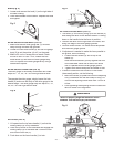
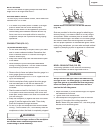
USING THE DUST CHUTE (FIG. Y)
To prevent fi re hazard, clean and remove sawdust
from under the saw frequently.
To prevent sawdust buildup inside the saw housing,
attach a vacuum hose (1) to the dust chute (2) at the
rear of the table saw. DO NOT operate the saw with
the hose in place unless the vacuum is turned on.
Fig.
Y
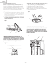
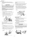
USING THE TABLE EXTENSION (FIG. Z)
NOTE:
Use scale on front rail for rip cuts up to 13.5”
. For
rip cuts greater than 13.5” set the lock the fence on the
13.5” mark. Unlock the extension table, and slide the
table with the fence to the desired dimension using the
scale on rear rail.
Release cam locking lever.
1. Slide the table extension to the desired measurement
and then tighten the cam locking lever.
Fig.
Z
WARNING
3
1
2
1
2
3
1
2