


5- 4
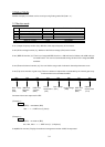
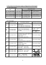
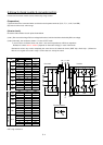
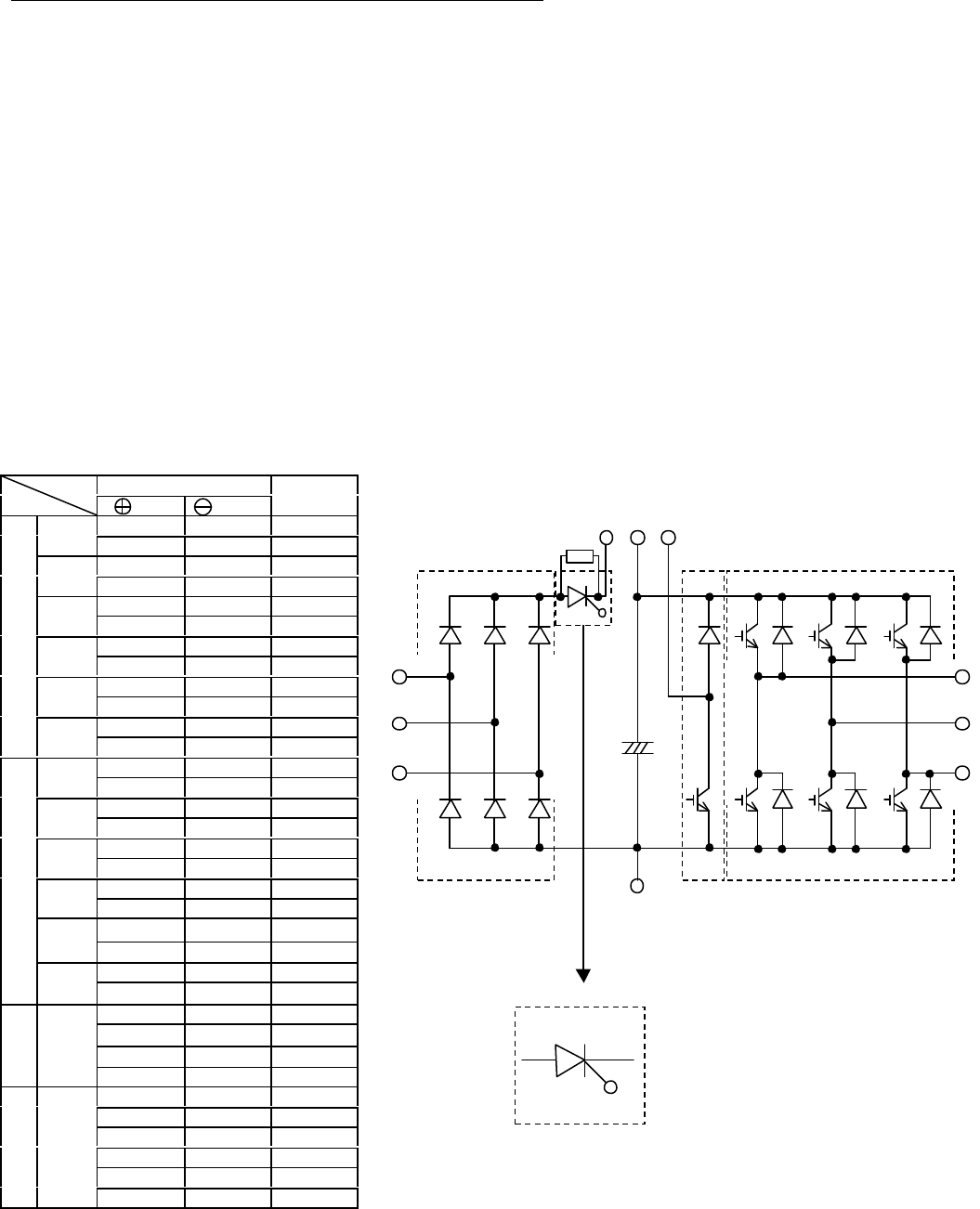
5.5 How to check inverter & converter portion
Inverter and converter module can be checked by using a tester.
(Preparation)
(1)Disconnect all the connected wires and devices to the power terminals (R, S, T, U, V, W, P and RB).
(2)Tester is to be set as 1ohm range.
(How to check)
Check the ON condition of each point shown below.
(note 1) Be sure to discharge DC bus voltage beforehand, which should be checked by DC bus voltage.
(note 2) Normally, the resistance shows ∞ in case of OFF mode.
In some cases resistance does not show ∞ due to the capacitance of DC bus capacitors.
Resistance shows 3ohm ~ 50ohm (depends on the tester voltage) in case of ON mode.
Resistance values may not be completely the same due to the electrical device (IGBT chip, diode chip…) difference.
But we can regard the result is okay if all the data are nearly the same.
Tester polarity
(Red)
(
Blk)
Measure
ment
R PD OFF
D1
PD R ON
S PD OFF
D2
PD S ON
T PD OFF
D3
PD T ON
R N ON
D4
N R OFF
S N ON
D5
N S OFF
T N ON
Converter
D6
N T OFF
U P OFF
TR1
P U ON
V P OFF
TR3
P V ON
W P OFF
TR5
P W ON
U N ON
TR4
N U OFF
V N ON
TR6
N V OFF
W N ON
Inverter
TR2
N W OFF
RB P OFF
P RB ON
RB N OFF
BRD
TR7
N RB OFF
A K OFF
A G OFF
K A OFF
K G ON
G A OFF
Thyristor
THY
G K ON
ON; Low resistance
OFF; High resistance
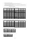
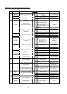
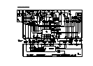
Converter Inverter
PD P
D1
D2 D3
D4
D5 D6
R
S
T
TR7
C+
RB
U
V
W
TR4 TR6 TR2
TR1 TR3 TR5
N
BRD
G
K
A
Thyristor portion
THY