


OM-2210 Page 10
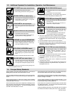
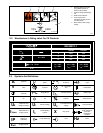
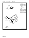
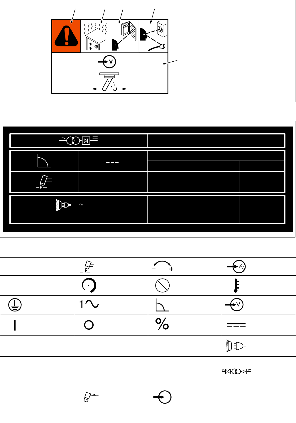
1 Warning! Watch Out! There
are possible hazards as
shown by the symbols.
2 Incorrect voltage will damage
unit.
3 Read Owner’s Manual.
4 Look at input power
receptacle and plug, and be
sure they match.
5 Move switch to match input
voltage.
4/96
S-176 481-A
115V 230V
1 2 3 4
5
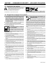
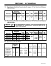
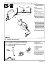
2-2. Manufacturer’s Rating Label For CE Products
S-181 265-A
EN 60974-1
X 100% 35%
16A/86V 27A/90V
U
0
= 255V
I
2
16A 27A
U
2
86V 90V
IP 23
50 Hz
1
I
1max
= 34AU
1
= 115V
I
1max
= 17AU
1
= 230V
I
1eff
= 20.5A
I
1eff
= 10.2A
1
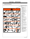
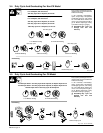
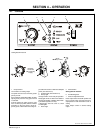
2-3. Symbols And Definitions
A
Amperes
Plasma Arc Cutting
(PAC)
Adjust Air/Gas
Pressure
Low Air Pressure
Light
V
Volts Increase
No − Do Not Do
This
Temperature
Protective Earth
(Ground)
Single Phase Constant Current Voltage Input
On Off Percent Direct Current
U
0
Rated No Load
Voltage (Average)
U
1
Primary Voltage
U
2
Conventional Load
Voltage
Line Connection
I
1max
Rated Maximum
Supply Current
I
2
Rated Welding
Current
X
Duty Cycle
Single Phase
Static Frequency
Converter-
Transformer-
Rectifier
IP
Degree Of
Protection
Loose Shield Cup Input
Hz
Hertz
I
1eff
Maximum Effective
Supply Current