


OM-2210 Page 15
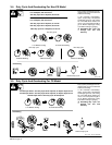
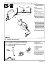
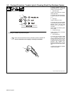
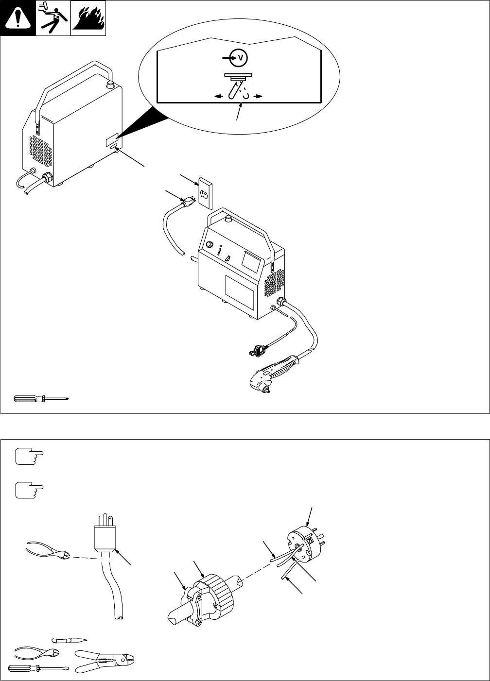
3-8. Setting Input Voltage Selector Switch And Connecting Input Power
ST-801 304-B / ST-801 319-B
Check input voltage available at site.
1 Input Voltage Selector Switch
Switch is accessible through slot in
rear panel.
2 Changeover Switch Label
Look at label to find correct switch
position.
Move switch to match input voltage.
3 Supplied 115 VAC Plug
If plug does not match voltage at re-
ceptacle or type of receptacle, install
suitable plug according to Section
3-9.
Y Be sure input power connec-
tion meets all applicable na-
tional, regional, and local
electrical codes.
4 115 Or 230 VAC Receptacle
(115 VAC Shown)
Y To use rated output (see
specifications), connect the
unit to an individual branch
circuit capable of carrying the
effective (eff) current for the
output being used. The unit
must have a properly sized
plug installed and the circuit
must be protected by proper-
ly sized fuses or circuit break-
ers.
Connect plug to proper receptacle.
Be sure receptacle can handle load.
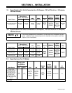
Tools Needed:
Rear Of Unit
1
3
4
S-176 481-A
115V 230V
2
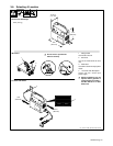
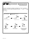
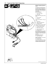
3-9. Installing Alternative Plug
1 Supplied 115 VAC Plug
Cut cord close to plug.
2 Alternative PLug (230 VAC
Plug Shown)
3 Load 1 (Brass) Terminal
4 Load 2 (Brass) Terminal
5 Ground (Green) Terminal
6 Outer Shell
7 Cord Grip
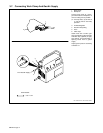
Strip cord jacket back enough to
separate conductors. Strip conduc-
tors enough to make good contact
with plug terminals. Make plug con-
nections and reinstall outer shell and
cord grip. Tighten assembly screws
onto shell. Do not overtighten.
Ref. ST-801 305-A / ST-801 611
This procedure is necessary if the unit is to be connected to a 230
VAC receptacle, or to a 115 VAC receptacle that requires a plug that
is different from the supplied plug.
Tools Needed:
1
6
7
2
3
4
5
See Section 3-8 for instructions on setting input voltage selector
switch for proper voltage.