


OM-2210 Page 16
SECTION 4 − OPERATION
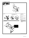
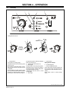
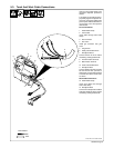
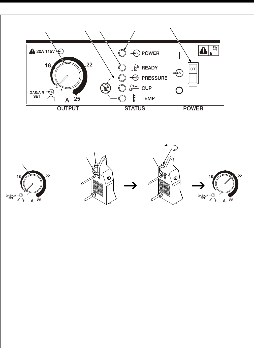
4-1. Controls
Ref. ST-801 306-B / Ref. SC-192 492
1 Output Control
Use control to set cutting output.
The yellow zone is for use on 20 A or greater
primary circuits.
Place control in Gas/Air Set position to safely
adjust gas/air pressure. Only gas/air circuit
is activated.
If 20-25 amperes of cutting output is used
with 115 VAC input power, and the overload
protection on the input power circuit fre-
quently opens, either reduce the cutting out-
put and/or the cut time or find more adequate
power (see Section 3-8).
2 Trouble Lights (See Section 5-2)
3 Ready Light
Use light to tell if unit is ready for operation.
Ready light comes on when Power switch is
placed in On position, indicating that all safe-
ty shutdown systems are okay.
If Ready light does not come on, check
Trouble Lights.
4 Power Light
5 Power Switch
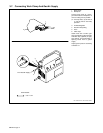
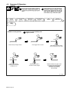
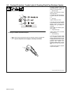
Setting Gas/Air Pressure
6 Air Filter/Regulator
7 Pressure Adjustment Knob
Place Output control in Gas/Air position and
turn on gas/air supply. Lift knob and turn to
adjust pressure. Push knob down to lock in
setting.
Place Output control in desired cutting
output.
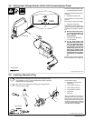
Setting Gas/Air Pressure
6
Set To
60 PSI (414 kPa)
7
Requires
70-150 PSI
(483-1034 kPa)
Supply
1 4
2
3
5
1