


OM-2210 Page 21
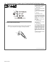
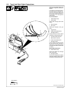
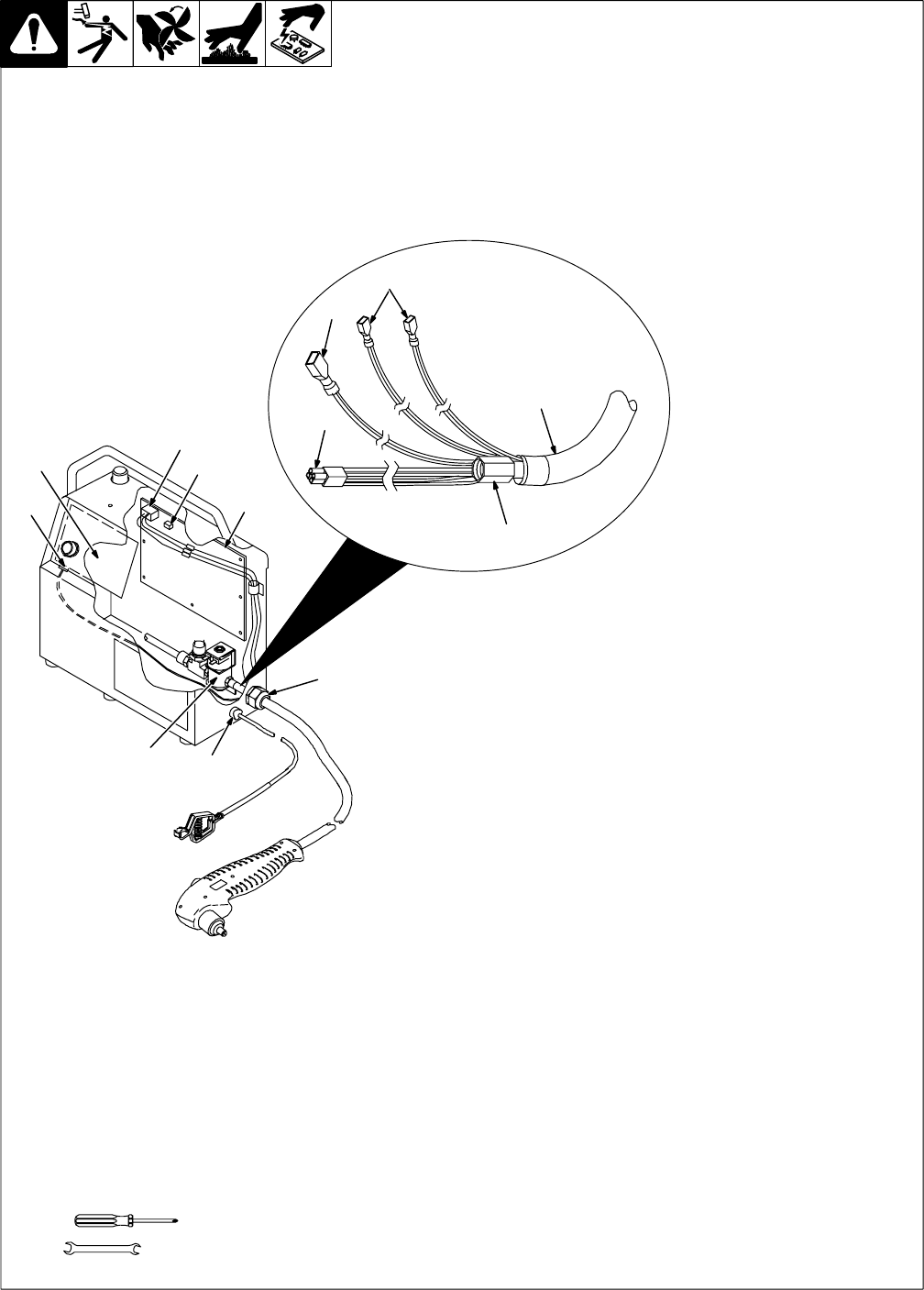
5-3. Torch And Work Cable Connections
If torch or work cable needs to be
removed or replaced, proceed as
follows:
Turn power Off, and disconnect in-
put power plug from receptacle. Re-
move top and screws holding front
panel in place. Without disconnect-
ing any plugs, move front panel to
allow access.
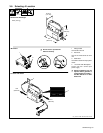
Torch Connections
1 Strain Relief Clamp
2 Torch Cable
Insert cable through strain relief
clamp.
3 Gas Connector
4 Gas Valve
Install gas connector onto gas
valve.
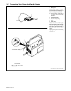
5 Plug PLG18
6 Safety Control Board PC2
7 Receptacle RC18
Connect PLG18 to RC18. Route
leads along existing lead bundle.
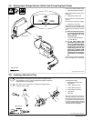
8 Female Friction Terminals
9 Male Friction Terminal
10 Power Control Board PC1
11 Receptacle RC4
Connect female terminals to leads
23 and 24 from RC4 (connect to
either lead). Connect male terminal
to lead 25 from RC4. Route leads
as shown.
Work Cable Connections
12 Strain Relief Clamp
Insert work clamp lead through
strain relief clamp.
13 Receptacle RC6
Connect work clamp lead to lead 20
from RC6 (leads not shown). Route
leads along existing lead bundle.
Tools Needed:
ST-801 423 / Ref. ST-801 300-B
5/8 in
1
4
3
12
2
5
9
8
11
13
6
7
10