


OM-249 498 Page 19
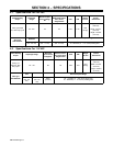
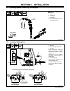
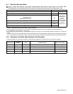
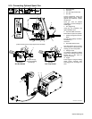
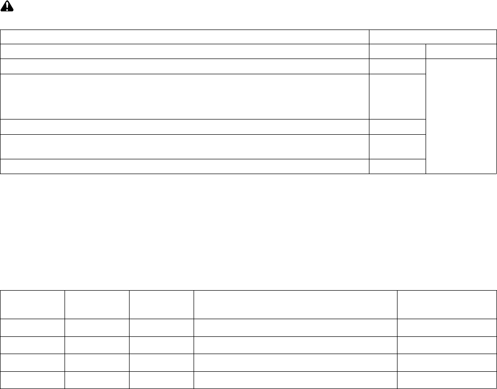
5-7. Electrical Service Guide
Failure to follow these electrical service guide recommendations could create an electric shock or fire hazard. These
recommendations are for a dedicated branch circuit sized for the rated output and duty cycle of the welding power source.
60 Hz Single Phase
Input Voltage (V) 230 Volts AC 115 Volts AC
Input Amperes (A) At Rated Output 24
A 20 ampere
individual branch
circuit
protected by
time-delay fuses
or circuit breaker
is required.
See Section 4-2
Max Recommended Standard Fuse Rating In Amperes
1
Time-Delay Fuses
2
30
Normal Operating Fuses
3
35
Min Input Conductor Size In AWG
4
14
Max Recommended Input Conductor Length In Feet (Meters)
53
(16)
Min Grounding Conductor Size In AWG
4
14
Reference: 2008 National Electrical Code (NEC) (including article 630)
1 If a circuit breaker is used in place of a fuse, choose a circuit breaker with time-current curves comparable to the recommended fuse.
2 “Time-Delay” fuses are UL class “RK5” . See UL 248.
3 “Normal Operating” (general purpose - no intentional delay) fuses are UL class “K5” (up to and including 60 amps), and UL class “H” ( 65 amps and
above).
4 Conductor data in this section specifies conductor size (excluding flexible cord or cable) between the panelboard and the equipment per NEC Table
310.16. If a flexible cord or cable is used, minimum conductor size may increase. See NEC Table 400.5(A) for flexible cord and cable requirements.
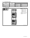
5-8. Extension Cord Data (Use Shortest Cord Possible)
. When calculating max. cord length, remember to include conductor length from line disconnect device to input power receptacle.
Input Voltage
Input Power
Phase
Hertz Conductor Size Max. Cord Length
115 V 1 60 14 AWG 25 ft (8 m)
115 V 1 60 12 AWG 55 ft (17 m)
115 V 1 60 10 AWG 100 ft (30 m)
230 V 1 60 14 AWG 53 ft (16 m)