


TABLE OF CONTENTS
SECTION 1 − SAFETY PRECAUTIONS - READ BEFORE USING 1.................................
1-1. Symbol Usage 1.......................................................................
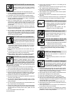
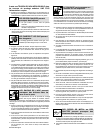
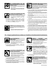
1-2. Arc Welding Hazards 1.................................................................
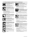
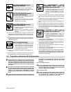
1-3. Additional Symbols For Installation, Operation, And Maintenance 3.............................
1-4. California Proposition 65 Warnings 4......................................................
1-5. Principal Safety Standards 4.............................................................
1-6. EMF Information 4.....................................................................
SECTION 2 − CONSIGNES DE SÉCURITÉ − LIRE AVANT UTILISATION 5...........................
2-1. Symboles utilisés 5.....................................................................
2-2. Dangers relatifs au soudage à l’arc 5......................................................
2-3. Dangers supplémentaires en relation avec l’installation, le fonctionnement et la maintenance 7.....
2-4. Proposition californienne 65 Avertissements 8..............................................
2-5. Principales normes de sécurité 9.........................................................
2-6. Informations relatives aux CEM 9.........................................................
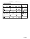
SECTION 3 − DEFINITIONS 11..................................................................
3-1. Symbols And Definitions 11...............................................................
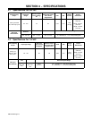
SECTION 4 − SPECIFICATIONS 12..............................................................
4-1. Specifications For 230 VAC 12............................................................
4-2. Specifications For 115 VAC 12............................................................
4-3. Duty Cycle And Overheating 13...........................................................
4-4. Volt-Ampere Curves 14..................................................................
SECTION 5 − INSTALLATION 15................................................................
5-1. Installing Nozzle, Contact Tip, And Adapter 15...............................................
5-2. Installing Welding Gun 15................................................................
5-3. Installing Work Clamp 16.................................................................
5-4. Process/Polarity Table 17................................................................
5-5. Changing Polarity 17....................................................................
5-6. Installing Gas Supply 18.................................................................
5-7. Electrical Service Guide 19...............................................................
5-8. Extension Cord Data (Use Shortest Cord Possible) 19........................................
5-9. Multi−Voltage Plug (MVP) Connection 20...................................................
5-10. Serial Number And Rating Label Location 21................................................
5-11. Selecting A Location And Connecting Input Power 21.........................................
5-12. Connecting 1-Phase Input Power For 230 VAC Input 22.......................................
5-13. Connecting 1-Phase Input Power For 115 VAC Input 23.......................................
5-14. Installing Wire Spool And Adjusting Hub Tension 24...........................................
5-15. Connecting Optional Spool Gun 25.........................................................
5-16. Threading Welding Wire 26...............................................................
SECTION 6 − OPERATION 27...................................................................
6-1. Controls 27............................................................................
6-2. Weld Parameter Chart 28................................................................
SECTION 7 − MAINTENANCE &TROUBLESHOOTING 29..........................................
7-1. Routine Maintenance 29.................................................................
7-2. Overload Protection 29..................................................................
7-3. Drive Motor Protection 29................................................................
7-4. Changing Drive Roll Or Wire Inlet Guide 30.................................................
7-5. Changing Nozzle, Contact Tip, Adapter And Liner, And Cleaning Gun Casing 31..................
7-6. Replacing Switch And/Or Head Tube 32....................................................
7-7. Troubleshooting Table 33.................................................................