


OM-249 498 Page 25
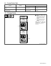
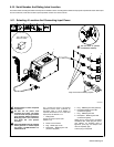
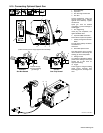
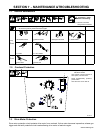
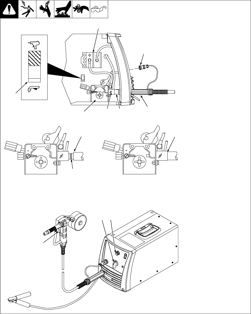
5-15. Connecting Optional Spool Gun
804 695-A / 804 696-A
1 Drive Assembly
2 Spool Gun
3 Gun Securing Thumbscrew
4 Gun End
Loosen thumbscrew. Insert end
through opening until it bottoms
against drive assembly. Tighten
thumbscrew.
Spool gun must be inserted
completely to prevent leakage of
shielding gas.
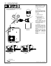
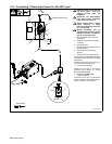
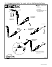
5 Gun Trigger Plug
Insert plug into receptacle, and
tighten threaded collar.
6 Spool Gun/MIG Gun Switch
Place switch in Spool Gun position.
7 Polarity Changeover Terminal
Block
To make proper polarity connection,
see Section 5-5.
Close door.
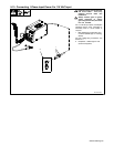
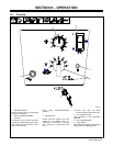
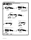
8 Wire Feed Speed Control
Wire feed speed control controls
rate at which the is fed through the
welding gun to the weld puddle.
9 Voltage Control
Arc voltage is controlled by welding
power source Voltage control (see
Section 6-2 or door chart for
appropriate setting).
10 Trigger
Press trigger to energize welding
power source contactor, start
shielding gas flow, and begin wire
feed.
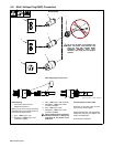
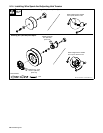
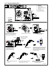
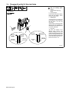
CorrectIncorrect
. Be sure that gun end is tight against drive assembly.
3
Gun Fully Seated
3
Gun Not Seated
Exposed O-rings
will cause shielding
gas leakage.
5
1
3
2
4
Spool Gun
MIG Gun
6
7
10
8
9