


OM-249 498 Page 22
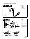
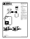
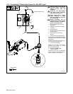
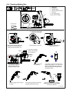
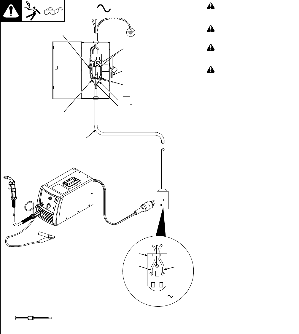
5-12. Connecting 1-Phase Input Power For 230 VAC Input
Ref. 250 332-A
! Installation must meet all National
and Local Codes − have only
qualified persons make this
installation.
! Disconnect and lockout/tagout
input power before connecting
input conductors from unit.
! Always connect green or green/
yellow conductor to supply
grounding terminal first, and never
to a line terminal.
! Special installation may be
required where gasoline or volatile
liquids are present − see NEC Ar-
ticle 511 or CEC Section 20.
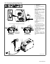
1 Black And White Input Conductor
(L1 And L2)
2 Green Or Green/Yellow Grounding
Conductor
3 Input Power Cord.
4 Disconnect Device (switch shown in
the OFF position)
5 Disconnect Device Grounding
Terminal
6 Disconnect Device Line Terminals
Connect green or green/yellow grounding
conductor to disconnect device grounding
terminal first.
Connect input conductors L1 and L2 to
disconnect device line terminals.
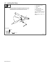
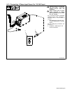
7 Over-Current Protection
Select type and size of over-current
protection using Section 5-7 (fused
disconnect switch shown).
8 Receptacle (NEMA 6-50R)
Customer Supplied
Close and secure door on disconnect
device. Remove lockout/tagout device,
and place switch in the On position.
4
3
L1
L2
1
=GND/PE Earth Ground
2
1
5
6
7
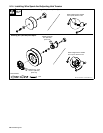
Tools Needed:
L1
L2
230 VAC, 1
8