


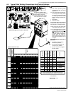
. A complete Parts List is available at www.HobartWelders.com
OM-240 438 Page 25
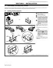
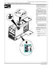
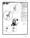
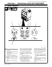
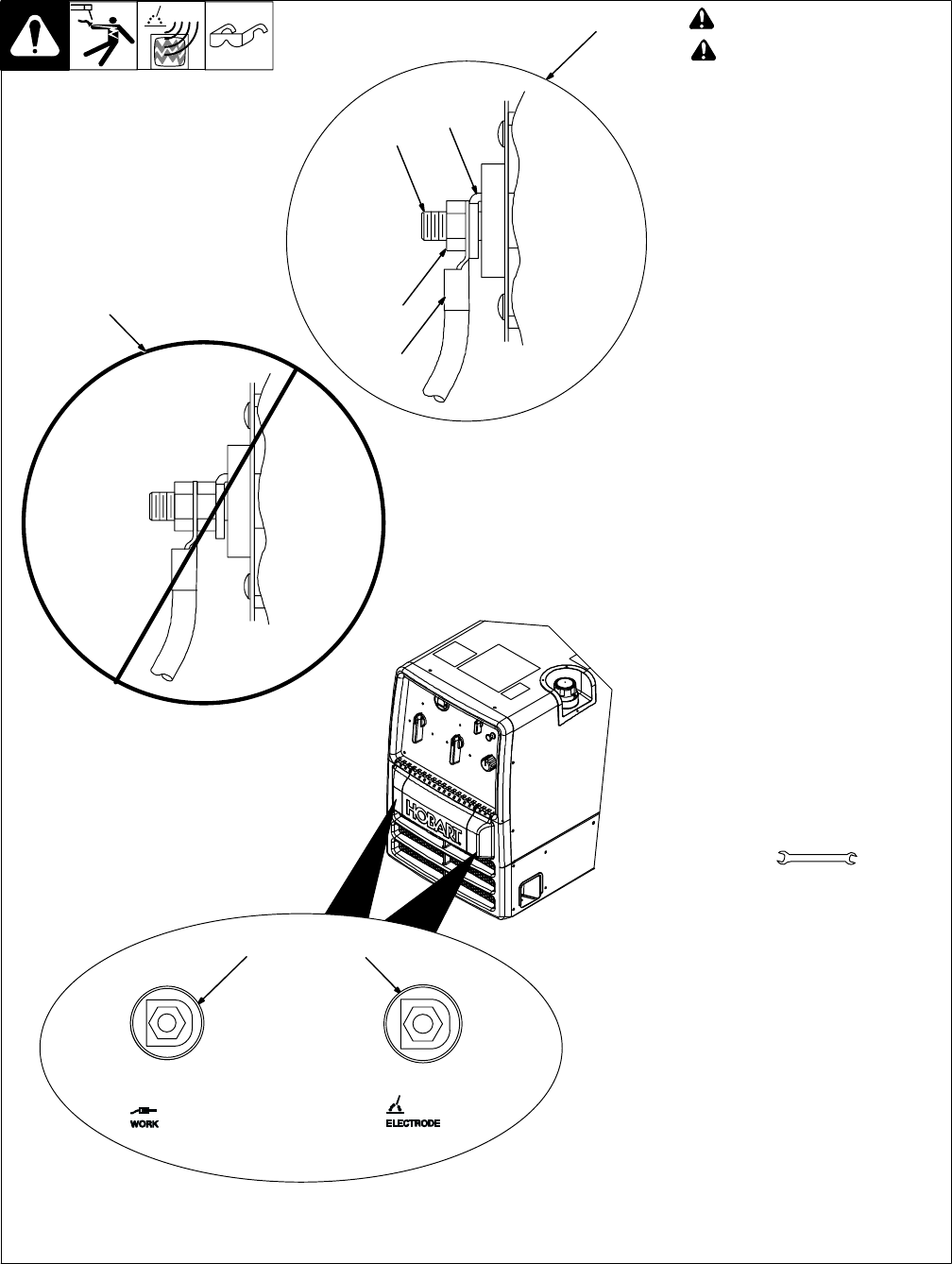
! Stop engine.
! Failure to properly connect
weld cables may cause exces-
sive heat and start a fire, or
damage your machine.
. Do not place anything between
weld cable terminal and cop-
per bar. Make sure that the sur-
faces of the weld cable termi-
nal and copper bar are clean.
1 Correct Weld Cable Installation
2 Incorrect Weld Cable
Installation
3 Weld Output Terminal
4 Supplied Weld Output Terminal
Nut
5 Weld Cable Terminal
6 Copper Bar
Remove supplied nut from weld out-
put terminal. Slide weld cable terminal
onto weld output terminal and secure
with nut so that weld cable terminal is
tight against copper bar.
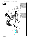
7 Work Weld Output Terminal
8 Electrode Weld Output Terminal
For Direct Current Electrode Positive
(DCEP), connect work cable to Work
terminal and electrode holder cable to
Electrode terminal.
For Direct Current Electrode Negat-
ive (DCEN), reverse cable connec-
tions
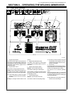
Use Process Selector switch to
select type of weld output (see
Section 6-1).
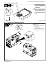
. See Sections 6-3for typical pro-
cess connections and control
settings.
5-8.
C
onnecting To Weld
O
utput Terminals
244 029-A / 281 080-A / 803 778-B
Tools Needed:
3/4 in.
6
4
5
3
78
1
2