


. A complete Parts List is available at www.HobartWelders.com
OM-240 438 Page 27
SECTION 6 − OPERATING THE WELDING GENERATOR
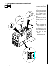
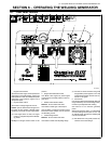
4
1
3
6
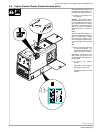
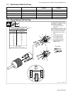
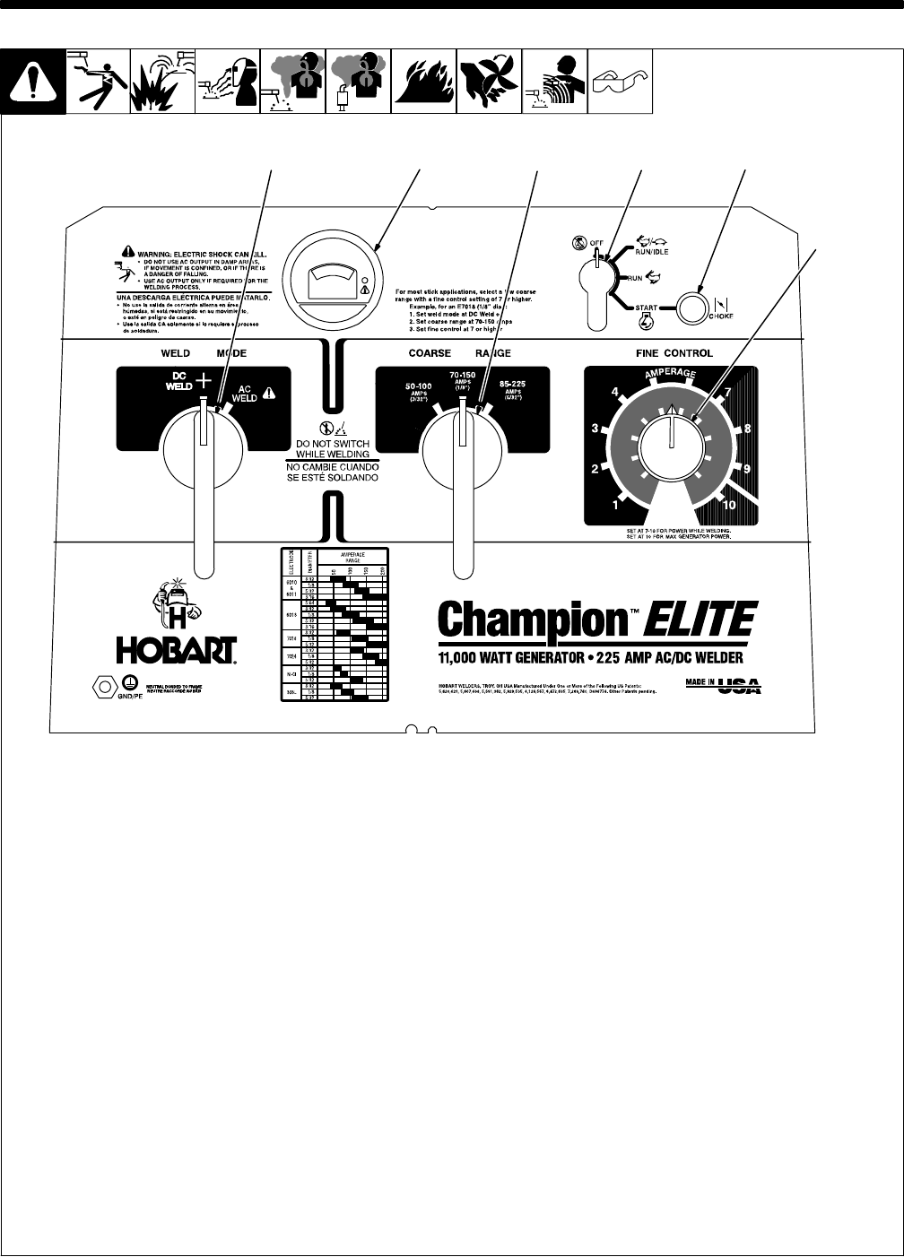
6-1. Front Panel Controls
281 080-A
1 Engine Control Switch
Use switch to start engine, select speed, and
stop engine. In Run/Idle position, engine runs
at idle speed at no load, and weld/power speed
under load. In Run position, engine runs at
weld/power speed.
2 Engine Choke Control
Use control to change engine air-fuel mix.
To Start: pull out choke and turn Engine Con-
trol switch to Start position. Release switch
and slowly push choke in when engine starts.
. If the engine does not start, let engine
come to a complete stop before attempt-
ing restart.
To Stop: turn Engine Control switch to Off
position.
3 Engine Hour Meter/Idle Control
Hour Meter: With engine off, place Engine
Control switch in Run/Idle position to view en-
gine hours.
4 Weld Process Selector Switch
NOTICE − Do not switch under load.
Use switch to select type of weld output.
Use DC Weld (+) position for Direct Current
Electrode Positive (DCEP). Use AC position
for alternating current.
5 Coarse Range Switch
NOTICE − Do not switch under load.
Use switch to select weld amperage range.
. For best arc starts and when using weld
and generator power together, use a low
Coarse Range setting with the Fine con-
trol set at 7 or higher.
6 Fine Control
Use control to select weld amperage within the
range selected by the Coarse Range switch.
Control may be adjusted while welding.
Set control at 10 for maximum generator
power.
Weld output would be about 110 A DC based
on control settings shown (80% of 70 to 150
A). Settings shown are typical for welding with
a 7018 (1/8) electrode.
. See Sections 6-3 for typical process con-
nections and control settings.
5
2