


OM-487 Page 13
SECTION 4 – INSTALLATION
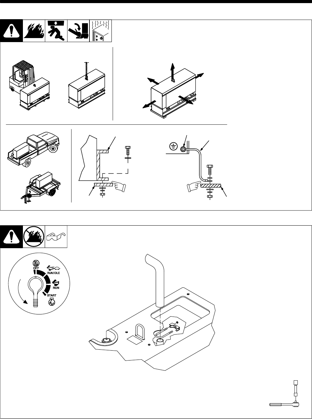
install1 10/00 – Ref. ST-800 652 / Ref. ST-800 477-A / ST-158 936-A / S-0854
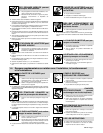
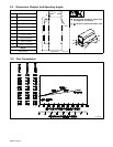
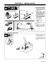
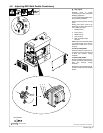
Y Do not weld on base. Weld-
ing on base can cause fuel
tank fire or explosion. Bolt
unit down using holes pro-
vided in base.
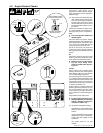
Y Always securely fasten
welding generator onto
transport vehicle or trailer
and comply with all DOT and
other applicable codes.
Y Always ground generator
frame to vehicle frame to pre-
vent electric shock and static
electricity hazards.
1 Generator Base
2 Metal Vehicle Frame
3 Equipment Grounding
Terminal
4 Grounding Cable
Use #10 AWG or larger insulated
copper wire.
Y If unit does not have GFCI re-
ceptacles, use GFCI-
protected extension cord.
1
2
Electrically bond genera-
tor frame to vehicle frame
by metal-to-metal contact.
GND/PE
3
4
2
OR
OR
18 in
(460 mm)
18 in
(460 mm)
18 in
(460 mm)
18 in
(460 mm)
18 in
(460 mm)
OR
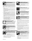
Movement Airflow Clearance
Location
Grounding
Y Do not lift unit from end.
4-1. Installing Welding Generator
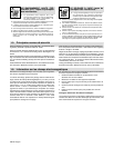
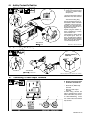
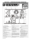
4-2. Installing Exhaust Pipe
ST-801 681 / Ref. ST-187 602-A
. Do not blow exhaust toward
rear of unit or air cleaner will re-
quire frequent service.
. Point exhaust pipe in desired
direction but always away from
front panel and direction of
travel.
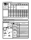
Tools Needed:
1/2 in