


OM-487 Page 18
SECTION 5 – OPERATING WELDING GENERATOR
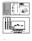
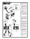
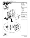
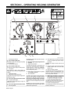
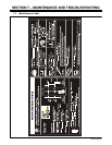
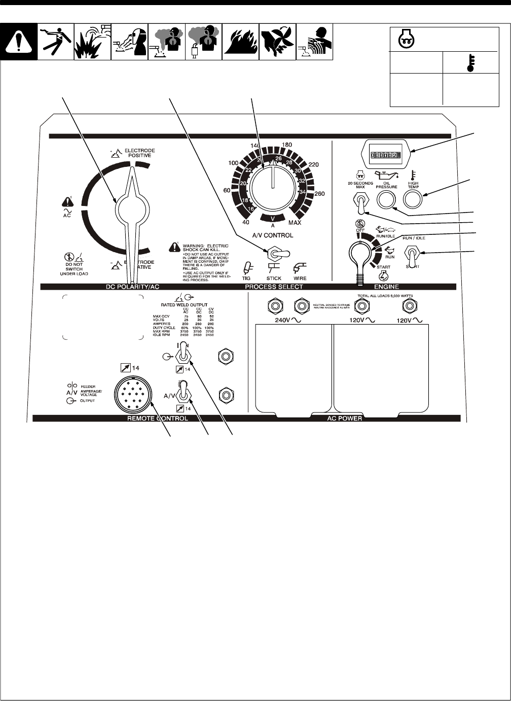
5-1. Front Panel Controls
Ref. ST-187 602-A
1 DC Polarity/AC Switch
Y Do not switch under load.
Use switch to select AC weld output or polarity
of DC weld output.
2 Process Select Switch
Y Do not switch under load.
Use switch to select output for weld process.
3 A/V Control
Use control to select weld voltage or
amperage. Control may be adjusted while
welding.
4 Engine Hour Meter
5 High Engine Temperature Light
Light goes on and engine stops if engine tem-
perature is too high.
Y Do not run engine until trouble is fixed.
6 Low Oil Pressure Light
Light goes on and engine stops if engine oil
pressure is too low.
Y Do not run engine until trouble is fixed.
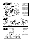
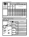
7 Glow Plug Switch
If necessary, push switch up before start-up
(see table above).
Y Do not use glow plugs longer than 20
seconds.
8 Engine Control Switch
Use switch to start engine, select speed, and
stop engine. In Run/Idle position, engine runs
at idle speed at no load, and weld/power
speed under load. In Run position, engine
runs at weld/power speed.
. Place switch in Run position to operate
most GMAW equipment.
9 Idle Lock Switch
Use switch to lock engine in idle speed during
start-up. In Start position and Engine Control
switch in Run or Run/Idle, engine is locked in
idle speed. In Run/Idle position and Engine
Control switch in Run/Idle, engine runs at idle
speed at no load and weld/power speed under
load.
To start: move idle lock switch and engine
control switch to Start. Release engine control
switch when engine starts.
. If the engine does not start, let the engine
come to a complete stop before attempt-
ing restart.
To Stop: turn Engine Control switch to Off
position.
. Close fuel valve to stop engine if Engine
Control switch does not work (see
Section 4-3).
10 Output (Contactor) Switch
Use switch to control remote contactor if con-
nected to remote 14 receptacle RC1 (see
Section 5-2). Place switch in Remote 14 posi-
tion if using remote contactor.
Y Weld output terminals are energized
when Output (Contactor) switch is in
On position and engine is running.
11 Remote Amperage/Voltage Switch
Use switch to select front panel or remote am-
perage/voltage control (see Section 5-2).
12 Remote 14 Receptacle RC3
Use receptacle to connect remote control (see
Sections 4-8 and 5-2).
t
0 s
10 s
20 s
70°F (21°C)
32°F (0°C)
–4°F (–20°C)
Glow Plug Time
1 2 3
4
5
6
7
8
9
11 10
12