


OM-487 Page 39
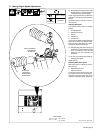
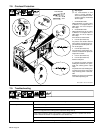
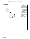
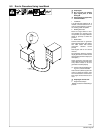
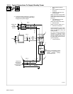
9-2. Run-In Procedure Using Load Bank
S-0683
Y Stop engine.
Y Do not touch hot exhaust
pipe, engine parts, or load
bank/grid.
Y Keep exhaust and pipe away
from flammables.
1 Load Bank
Turn all load bank switches Off. If
needed, connect load bank to 115
volts ac wall receptacle or genera-
tor auxiliary power receptacle.
2 Welding Generator
Place A/V range switch in maxi-
mum position, A/V control in mini-
mum position, and Output Selector
switch (if present) in either DC
position.
3 Weld Cables
Connect load bank to generator
weld output terminals using proper
size weld cables with correct
connectors. Observe correct
polarity.
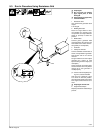
Start engine and run for several
minutes.
Set load bank switches and then
adjust generator A/V control so load
equals rated generator output (see
nameplate).
Check generator and load bank
meters after first five minutes then
every fifteen minutes to be sure
generator is loaded properly.
. Check oil level frequently dur-
ing run-in; add oil if needed.
After one hour (minimum) place A/V
control in minimum position, then
turn off load bank to remove load.
Run engine several minutes at no
load.
Y Stop engine and let cool.
4 Engine Exhaust Pipe
Repeat procedure if wetstacking is
present.
2
3
4
1