


12
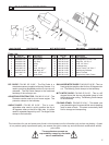
IF ANY PARTS ARE MISSING OR DAMAGED, PLEASE
CONTACT YOUR Husqvarna CUSTOMER SERVICE
FOR INSTRUCTIONS. CALL 1-800-288-5040
Tools required: Your new saw can be completely as-
sembled with the Wrench (E) provided.
Qty Part Number Description Size
1 542 16 16-41 Wrench 15/16” x 9/16” x 1/2”
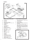
• Set the Frame Assembly (1) on a at surface or on a
Husqvarna folding stand.
• Install the Water Pan Assembly (2) between the four
Pan Guides (A) on the Frame Assembly (1). Locate
the Pan (2) with the Drain Plug (B) at the operating
end with the two Stops (C) located on the bottom of
the Pan (2) straddling the front leg of the Frame (1).
The Water Pan Assembly (2) should slide freely back
and forth on the Guides (A) with little lateral move-
ment. Adjust Guides if needed.
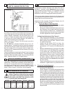
Install the Cutting Head Assembly (1):
1. Set the Cutting Head Assembly (3) on the pivot
bar up between the Set Collar (U) and the ad-
justable Cutting Head Position Limiter (V). See
Figure 2. These components have been pre-set
at the factory to align the blade with the slot in
the center of the cart; this is adjustable.
See Alignment Procedures, section 8.
2. Using the 5/16” Capscrews and Lockwashers
provided, install the two Bearing Caps (D) to
the bottom of the Cutting Head (3). To secure
the Cutting Head (3) to the pivot bar, tighten the
Capscrews with a 1/2” wrench or use the Wrench
(E) provided. For plunge-cutting, leave the Bear-
ing Caps (D) free enough to allow the Cutting
Head (3) limited movement up or down.
3. Insert the Locking Knob (F) with 5/16” at-
washer through the slotted Lockbar (G) into
the tapped hole in the belt guard. This is used
to set the cutting depth of the blade. See sec-
tion 5.
Set-up with the Torsion Spring (W):
With the Cutting Head installed on the pivot bar,
rotate the Torsion Spring (W) until the inside
spring loop (W1) engages around the lower
edge of the motor platform. Loosen the 5/16”
Capscrew (X) in the spring Tension Adjuster
(Y) and move it to engage the Roll Pin (Z) into
the outside spring loop (W2). Set the desired
tension for your plunge cutting and tighten the
Capscrew (X) to secure the Tension Adjuster to
the pivot bar. Use the ats on the back of the
Tension Adjuster with a adjustable wrench if
extra tension is needed.
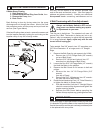
Water Pump Assembly (5) Set-up:
1. Remove the Water Pump (H), Hose Barb (J),
the Water Control Valve (K) and Water Tube
Assembly (L) from their carton. Thread the Hose Barb
(J) on the water pump outlet, hand tighten.
2. Slide the Control Valve (K) onto the exible
plastic tubing and push the open end onto the
Hose Barb (J).
3. Set the Water Pump Assembly (5) in the deep
end of the pan beneath the belt guard. Note:
The water pump inlet screen must be sub-
merged in order to properly pick up water.
4. Place the Water Tube Assembly (L) to the back
of the Blade Guard (M) and insert the two 1/4”
plastic nozzles (L2) into the two Ports (N) on the
side of the Blade Guard (J). Route water tubing
sa as to prevent interference with the Cart (4).
5. Insert the male plug into the Receptacle on the
motor. The Water Pump (H) will start when the
motor is turned on. For dry cutting, the water
pump should be unplugged or removed to pre-
vent damage to the pump.
NOTE: THE MOTOR WATER PUMP OUTLET IS
NOT TO BE USED AS A GENERAL PURPOSE
CONVENIENCE OUTLET. USE FOR CONNECTION
OF THE SUPPLIED WATER PUMP ONLY.
WATER PUMP SAFETY GUIDELINES
Always plug the saw power cord into a GFCI
outlet when using. If a GFCI type outlet is not
available, use a plug-in type GFCI plugged
into a properly grounded outlet. Do not use
any temporary plug adapters.
• The water pump is equipped with a ground electrical
plug, to reduce the risk of possible shock. Be sure
to connect to a properly grounded type receptacle.
• Never pick the water pump up out of the water when
it is plugged in.
• DO NOT EVER use the water pump to pump any-
thing but water.
• Never service the pump when it is still plugged in.
• Never let the pump operate dry. It is self-cooled by
pumping water. Dry use will cause the pump to fail.
• Maintain regularly and clean out debris from intake
screen.
• Check the power cord for nicks or frays and never
try to alter the power cord in any way.
Installation & Removal of Cutting Blade:
Always set the Motor Switch to OFF prior to
mounting the blade.
Be sure you are using the correct blade for the material
being cut. For example, blades are available for cutting
materials such as wall tile, quarry tile, marble, slate and
similarly hard materials. For the best results, always
use genuine Husqvarna diamond blades. Contact your
nearest dealer to select the correct blade for your spe-
cic cutting needs.