


16
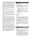
The operator must
wear protective clothing
appropriate to the work he
is doing.
Any persons not involved in the work should
leave the area.
Use only blades marked with a maximum
operating speed greater than the blade shaft
speed.
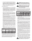
Use: Wet or Dry sawing of masonry and refractory materi-
als such as brick and block. Not for use with material
shapes that are unstable on a at surface, such as rocks,
natural stone, molded shapes, etc.
Tools: Diamond blades — dry or water cooled,
Ø: 10" (250 mm), 12" (300 mm), and
14" (350 mm), with Arbor Ø 1" (25.4 mm).
(For information contact your Dealer)
Depth of Cut (Maximum):
5.00" (127 mm) with Ø 14" (350 mm) blade
Maximum Material Size:
8" x 8" x 16" (20.3 x 20.3 x 40.6 cm) block
Block must be rotated 180 degrees to complete
cutting through 8" (20.3 cm) depth.
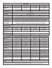
Nominal Weight: See “Specications”
Operating Weight: See “Specications”
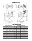
Dimensions: See “Saw Dimensions”
Blade Guard Capacity:
Electric Models: 10" (250 mm), 12" (300 mm) &
14" (350 mm) Ø Blades.
Gas Model: 14" (350 mm) Ø Only. Smaller Blade
Diameter not recommended because blade will not
cut through material. Head tilt is limited because the
maximum engine inclination angle is 20 degrees.
Before starting up the machine, make sure
you read this entire manual and are familiar
with the operation of this machine.
The working area must be completely clear,
well lit and all safety hazards removed.
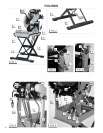
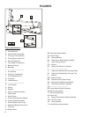
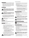
All Models: (FIGS. 1, 2, 3, 4 and 13)
• When unpacked, this unit consists of four (4) major parts:
Pan Weldment (A), Head Platform Assembly (B) Cart
Assembly (C) and Lifting Handles (XX) (FIG. 1).
• If this unit is to use the optional Folding Stand (D) (See
Fig. 1) and Skid Kit (E) (See FIG. 2) assemble these
items rst. Follow the instructions provided with these
options.
• Set the Pan Weldment (A) on a table or on the optional
Folding Stand / Skid Kit (D / E) as shown in FIG. 1. It is
very important that the Pan Weldment (A) be assembled
on the Folding Stand (D) as shown in Fig. 1, or the
optional Foot Pedal Kit (F) CAN NOT be assembled
onto the unit.
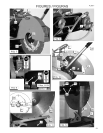
• Attach the Lifting Handles (XX) as shown in FIG. 13 using
the Mounting Hardware (YY) that is provided. Mount the
hardware with the nuts toward the outside of the frame
and the capscrews toward the inside of the frame. This
will simplify mounting the saw on the Optional Stand.
Four washers are to be assembled over the "slots" in
the frame. Four of the eight washers are not required,
but can be used if desired over the remaining holes.
Tighten the hardware securely.
WARNING: Make sure that Handle Mounting
Hardware (YY) is securely tightened before
transport of the frame or re-assembly of the
complete unit. Failure to do so could result
in serious injury to the operator or other
persons in the work area!
• Remove the Cart Assembly (C) from its shipping
carton. Set the Cart Assembly (C) onto the Pan Weld-
ment (A) so that the wheels of the Cart Assembly (C) roll
along the sides of the Pan Weldment (A) (FIG. 1).
• Make sure that the left and right Bearing Clamps (G)
on the Pan Weldment (A) are pivoted into their lowered
position (FIG. 3). Carefully pick up the Head Platform
Assembly (B) and mount it to the Pan Weldment (A) such
that the Bearings (H) (on Head Platform) are resting in
the Pivot Blocks (J) (on Pan Weldment) and that the
blade shaft end of the Head Platform (B) is resting on
the Cart Assembly (C) (FIG. 3).
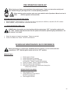
These signs will give
advice for your safety
Before leaving our factory every machine is
thoroughly tested.
Follow our instructions strictly and your machine
will give you long service in normal operating
conditions.
MANDATORY
INDICATION
INFORMATION
INSTRUCTION
WARNING
PROHIBITION
1 Features
2 Assembly