


21
material placed on the Cart Assembly (C). If the saw
or Head Platform Assembly (B) is dropped or damaged
the blade could become mis-aligned so that it no longer
cuts “squarely” through the material. If this occurs the
blade shaft should be re-aligned so that the saw will
produce “square” cuts. If the Blade is severely out of
alignment [1/16" (1.5 mm) or more] the Head Platform
Assembly (B) may need to be “bent” so that the blade is
closer to being aligned. In cases of severe damage the
Head Platform Weldment should be replaced. Precise
alignment can be achieved by using Shims (HH) of
various thickness. See the parts list section of this
document for the part number and thickness
information about the shims.
⇒ Note: Before starting to align the head platform make
sure the blade is at and is NOT bent or damaged!
⇒ Note: When aligning the blade against the square be
sure to allow for the difference in thickness between the
diamond segment and the center core of the blade!
1. Make sure the Conveyor Cart (C) rolls freely along
the pan. If the pan is damaged it must be repaired or
replaced before the blade can be aligned. Lock the
Head Platform Assembly (B) securely in a horizontal
position.
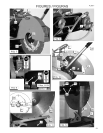
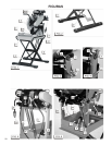
2. PARALLEL ALIGNMENT (Figure 11): Supply a Square
(GG) and place it on the Conveyor Cart (C) and roll the
cart while the Square (GG) rests against the blade. Ad-
just the Blade Shaft into Parallel Alignment (if required)
by putting Shims (HH) between the blade shaft housing
and the head platform weldment at location “A1” (Figure
11). Loosen, but do not remove, the Capscrews (JJ)
holding the blade shaft in position. Slide a shim, of the
proper thickness, upward and position around the thread
of one of the capscrews. Tighten the hardware and
check the blade alignment. Add more shims if required
until the blade shaft has Parallel Alignment.
3. PERPENDICULAR ALIGNMENT (Figure 12): Place
the Square (GG) on the Conveyor Cart (C) so that it
is against the saw blade and is below the center of
the blade shaft. If the Square (GG) does NOT contact
the Diamond Blade (DD) along the entire height of the
square, the blade shaft must adjusted into Perpendicular
Alignment. Adjust the blade shaft by putting Shims (HH)
between the blade shaft housing and the head platform
weldment at location “B2” (Figure 12). Loosen, but do
not remove, the Capscrews (KK) that hold the blade
shaft in position. Slide a shim, of the proper thickness,
inward and position around the thread of one of the
capscrews. Tighten the hardware and check the blade
alignment. Add more shims if required until the blade
shaft has Perpendicular Alignment.
• Never transport the saw with the cutting head positioned
on the frame. The movement can knock the head out
of alignment.
• When storing for an extended period of time, use a
wire brush to remove hard, caked sludge. Clean and
thoroughly lubricate moving parts - so on the next job
the saw is ready for operation.
• Drive belts must be tight. When the belts are loose,
power is lost. Replace worn belts without delay!
• The blade must t the arbor snugly - especially diamond
blades. Otherwise, pounding will occur and this will
seriously damage the blades. If the arbor shoulder is
grooved where the diamond blade has bound in the cut
as the shaft has continued to turn, the arbor must be
replaced, or the blade life will be severely shortened.
All Models (FIGS. 5 & 6):
• Check V-Belt tension when unit is new and never set
belt tension beyond this point.
• The saw is equipped with high tension V-Belts. The
belts are properly tensioned at the factory, but after a few
hours of operation they will stretch and become loose.
• Tensioning Blade Shaft V-Belts:
1. Loosen the four (4) capscrews that attach the
motor (Electric Models), or the Engine Platform
(Gasoline Models).
2. Tighten the Belt Tensioning Bolt (SS) at the rear
of the saw until the belt a tightened to the original
factory tension.
3. Re-tighten the four (4) capscrews that attach the
motor (Electric Models), or the Engine Platform
(Gasoline Models).
Electric Model:
• See “All Models” from above text.
Gasoline Model:
• Blade Shaft V-Belt Tension (FIG. 6): Excessive belt
tension will cause engine misalignment because the
engine is mounted on four (4) rubber vibration Isolators
(W). Stop tensioning the blade shaft drive V-belt when
the center section of the front right hand Isolator (W)
begins to separate from its mounting plate. Tensioning
the Blade Shaft drive V-Belt beyond this point is not
recommended because the front right hand Isolator (W)
will not function properly.
• Water Pump V-Belt (EE) Tension (FIG. 8): May need
to be tightened after a few hours of operation. Over
time this V-Belt may stretch beyond the length of the
adjustment slot. If this happens simply remove the
V-Belt and take out one or more links (as required) from
its length.
9 Important Advice
8 V-Belt Tension