


17
• Pivot the left and right Bearing Clamps (G) into their up-
per position, and tighten the Knobs (K) [or Capscrews
(K) depending on the date of manufacture] until the Head
Platform (B) is secured to Pan Weldment (A) (FIG. 4).
• Note: If the unit uses Capscrews (K) to hold the Bearing
Clamps (G) in place, tighten them with the 1/2" end of
the Wrench (LL) provided with the saw (FIG. 4).
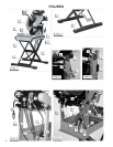
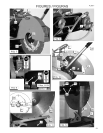
Electric Models (FIG. 5):
• Install the Counterbalance Arm (L): Place the slotted
end of the Counterbalance Arm onto the stud located
on the Left Hand Rear Corner of the Head Platform
Assembly (B). Be sure to put 1/2" Washers on both side
of the ARM before installation. Note that the lower hole
of the ARM is positioned toward the Pan Weldment (A).
A capscrew holds the ARM to the brackets on the back
of the Pan Weldment through this lower hole.
• Install the Lock Handle (P) onto the stud on the Left
Hand corner of the Head Platform Assembly (B).
Tighten the Lock Handle (P) so that the Head Platform
Assembly (B) is securely locked with the blade shaft in
the maximum upper position.
• Make sure that the Eyebolt (R) is securely fastened
onto the Arm (L), and note that the eye of the Eyebolt
(R) should be aligned with the spring mounting hole in
the Head Platform Assembly (B).
• Attach the top of the Spring (Q) through the hole in the
rear ange of the Head Platform Assembly (B). With a
tool (such as a screwdriver), stretch the lower end of the
Spring (Q) so that it is hooked over the Eyebolt (R).
• Install the Water Pump (U) by plugging its Electrical
Cord (NN) into the electric motor pigtail cord. Install the
hose barb tting onto the Water Pump (U), then push
on the hose. Route hose & electrical cord above the
cross-brace of the Pan Weldment (B) to avoid contact
with the blade during operation and so that the splash
curtain can be easily installed (NOT as shown in Figure
5). Place the Electric Water Pump (U) in the bottom
of the Pan Weldment (A). Hook the top of the Splash
Curtain (MM) over the head pivot bar, & place the
bottom of the Splash Curtain (MM) in the pan
(Fig. 1).
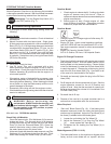
• Single phase masonry saw motors are furnished with
the correct NEMA configuration Plug (OO) on the
motor pigtail. The matching connectors are as fol-
lows:
To change operation to either 115, or 230 V, the 1-1/2 and
2 HP motors have a voltage change switch mounted on the
terminal box. This switch must be changed to either 115, or
230 Volt, to match the voltage supply. Local electrical codes
may require changing the plug on the motor to the proper
NEMA connector to match the voltage supply.
WARNING: Always make sure the saw is
connected to a properly grounded electrical
outlet. Failure to comply with this warning
could result in serious bodily injury or death!
WARNING: DO NOT operate on low voltage!
Low voltage causes loss of power, motor
overheating, and possibly motor winding
burnout. Voltage should be checked at the
motor while it is operating.
Good motor performance depends on proper voltage.
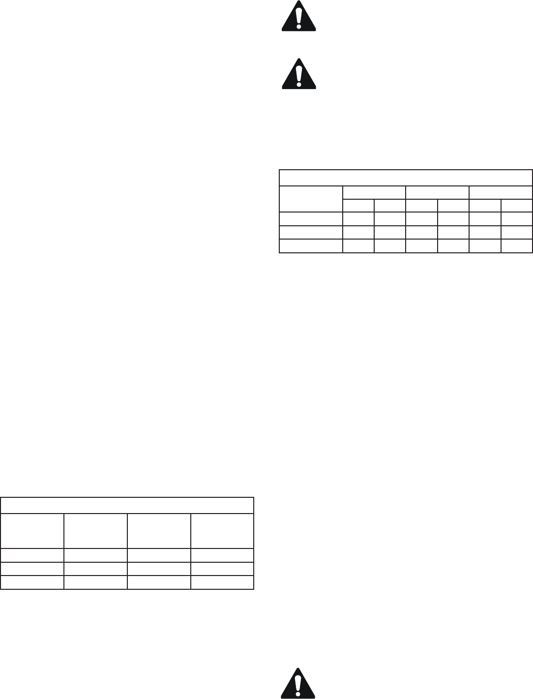
Extension cords that are too long and / or too small reduce
the voltage to a motor under load. Use extension cords NO
SMALLER than the sizes indicated in the chart shown:
Gasoline Model (Fig. 6):
• Assemble the Upper Spring Support (FF) using the
two (2) 3/8"-16UNC x 1.00" Long Capscrews and 3/8"-
16UNC Locknuts provided.
• Install the Counterbalance Arm (L). Loosely assemble
the 3/8" x 1.00" Long Capscrew (M) and 3/8"-16UNC
Locknut through the Lower Bracket (N) and the lower
end (13/32" diameter hole) of the Counterbalance
Arm (L).
• Raise the Head Platform Assembly (B) until the slot in
the Arm (L) can be put onto the 1/2" Stud on the Up-
per Spring Support (FF). Be sure to install the 1/2" at
Washers (Supplied) on both sides of the Arm (L).
• Mount and secure the Lock Handle (P) onto the 1/2"
Stud of the Upper Spring Support (FF). Tighten the
3/8" x 1.00" Long Capscrew (M) and 3/8"-16UNC
Locknut previously installed at the Lower Bracket (N).
• Install the upper end of the Spring (Q) in the hole in
the rear of the Upper Spring Support (FF). Loosen the
Lock Handle (P) and pivot the Head Platform Assembly
(B) so that the blade shaft is in the upper position, then
tighten the Lock Handle (P) securely. Using a tool (such
as a screwdriver or pliers) stretch the lower end of the
Spring (Q) so that it is secured into the Eyebolt (R) on
the Lower Bracket (N).
• Install the hoses to the water pump. They must be
connected together as shown in the parts list section of
this document. Place the Strainer (S) in the bottom of
the Pan Weldment (A) after connecting the hose. Hook
the top of the Splash Curtain (MM) over the head pivot
bar, & place the bottom of the curtain in the pan
(FIG. 1).
• When the unit is fully assembled, but before starting
the engine, verify that the engine does NOT exceed 20
degrees angle of inclination in any position of the Head
Platform [Use an angle measuring gauge (customer
supplied) held at against the Engine Platform (AA)].
CAUTION: Engine inclination angles greater
than 20 degrees could cause severe engine
damage and void your engine warranty!
EXTENSION CORD SIZE (A.W.G. Minimum)
Motor
HP
50 ft Long 75 ft Long 100 ft Long
115 V 230 V 115 V 230 V 115 V 230 V
1-1/2 HP #10 #14 #10 #14 #10 #14
2 HP #10 #12 #10 #12 #10 #12
3 HP --- #10 --- #10 --- #10
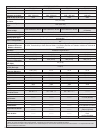
Electric Motor Plugs & Connectors
Motor
Wired For
Voltage
Motor Pigtail
Plug
(NEMA No.)
Connector
Required
(NEMA No.)
1-1/2 HP 115 V L5-20P L5-20R
2 HP 230 V L6-15P L6-15R
3 HP 230 V L6-30P L6-30R