


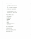
8.
Align holes on bed with those in the stand top
and fasten with eight hex socket cap screws
(5/16"x1") , eight lock washers (5/16"), and
eight nuts (5/16") supplied. Note: Two larger
hex socket cap screws and washers will be
used later to attach the bed extension to the
bed.
9.
Tighten eight hex socket cap screws with a hex
wrench.
1O. Tighten all stand hardwaremakingsure it is
stable on the shop floor.
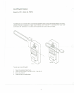
11. Attach bed extensionto bed usingtwo hex
socket cap screws (3/8"x1") and two lock
washers (3/8") supplied.
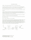
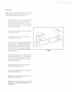
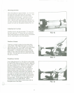
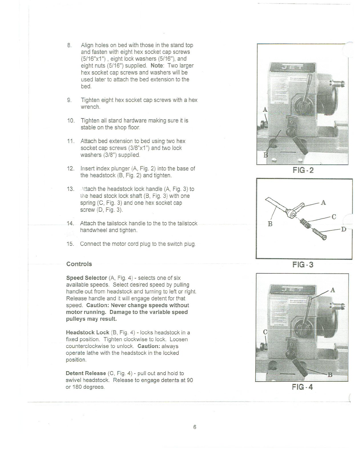
12. Insert index plunger(A, Fig. 2) into the base of
the headstock (B, Fig.2) and tighten.
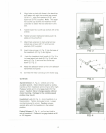
13. \ttach the headstock lock handle (A, Fig.3) to
the head stock lock shaft (B, Fig. 3) with one
spring (C, Fig. 3) and one hex socket cap
screw (0, Fig. 3).
14. Attach the tailstock handleto the to the tailstock
handwheel and tighten.
15. Connect the motor cord plug to the switch plug.
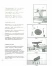
Controls
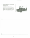
Speed Selector (A, Fig. 4) - selects one of six
available speeds. Select desired speed by pulling
handle out from headstock and turning to left or right.
Release handle and it will engage detent for that
speed. Caution: Never change speeds without
motor running. Damage to the variable speed
pulleys may result.
Headstock Lock (B, Fig. 4) -locks headstockin a
fixed position. Tighten clockwiseto lock. Loosen
counterclockwise to unlock. Caution: always
operate lathewith the headstock inthe locked
position.
Detent Release (C, Fig. 4) - pull out and holdto
swivel headstock. Releaseto engage detents at 90
or 180 degrees.
,- ._~- .--.
..- _. ..~- - ~_. -- ,,-
6
...-.-----------------------
FIG-2
~A
B -~c --'
~D--
FIG-3
FIG-4