14
Front Guide Rail
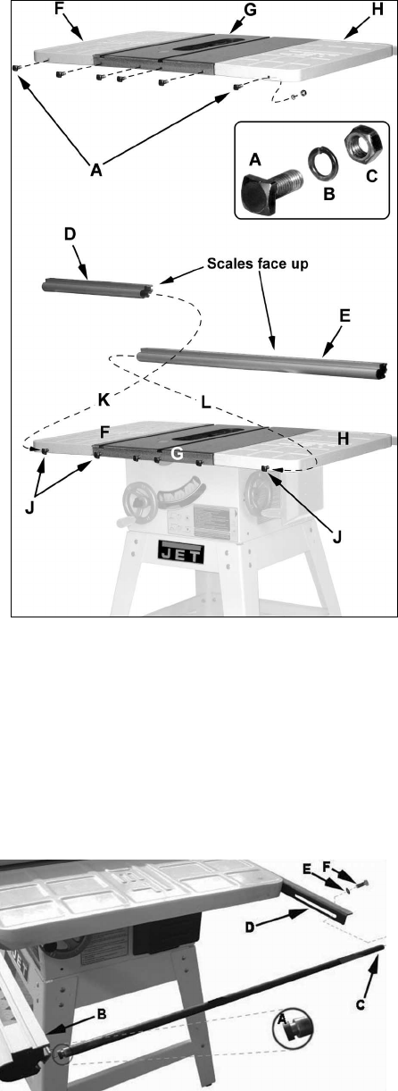
Referring to Figure 9:
Required Fastening Hardware (see also inset):
A – 6 ea – Square Head Bolt (M8)
B – 6 ea – Lock Washer (M8)
C – 6 ea – Hex Nuts (M8)
Required Tools:
– 12mm wrench
1. Place six square head bolts (A) through the
mounting holes on the front of the left
extension (F), table (G) and right extension (H).
2. Place lock washers (B) and hex nuts (C) on the
threaded ends of the bolts protruding through
the extensions and table. Just start the hex
nuts but do not tighten.
3. Position all six bolts so that approximately 1/4"
of thread is visible between the bolt heads and
extensions/table (J).
4. Slide the short rail (D) onto the front edge of
the extension and table from left to right (K).
The back edge of the rail should make contact
with the front edge of the extension and table
and the square head bolts should slide into the
groove on the back side of the rail.
5. In the same manner described in step 4, slide
the long rail (E) onto the front edge of the
extension and table from right to left (L).
6. Slide the short and long rail sections together
so they become one piece. The protruding pins
from the short rail should insert into the
corresponding openings in the long rail.
7. Position the entire rail assembly so the left end
of the rail is about 0.75” in from the edge of the
left extension.
8. Hand-tighten only the hex nuts (C) that secure
the front rail to the table.
Support Rod
Referring to Figure 10:
1. Place the tenon end (A) of the support rod into
the slot (B) of the front rail.
2. Secure the tapped and threaded end (C) of the
support rod to the rear rail (D) with the M6 flat
washer (E) and M6 hex cap screw (F)
provided.
Figure 9
Figure 10


