


17
Table Insert
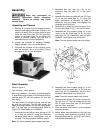
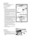
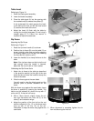
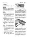
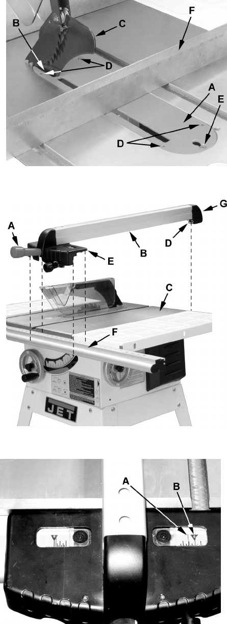
Referring to Figure 16:
1. Raise the blade guard assembly.
2. Lower the blade completely.
3. Place the table insert (A) into the opening with
the notched end (B) towards the splitter (C).
A clip underneath the notch secures the insert
to the table at the rear; an M5 flat head screw
(E) secures the insert at the front.
4. Adjust the insert (A) flush with the table by
turning four leveling setscrews (D) and using a
straight edge (F). A 2.5mm hex wrench is
required to adjust the setscrews.
Rip Fence
Attaching the Rip Fence
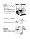
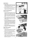
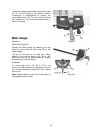
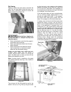
Referring to Figure 17:
1. Raise the rip fence handle (A) as shown.
2. Position the rip fence (B) over the table (C) as
shown, holding up the front end while engaging
the holding clamp (D) to the rear, then lowering
the front end (E) onto the rail (F).
3. Lower the handle (A) to clamp the fence to the
table.
Note: If the rip fence does not hold onto the rail
tight enough when the handle is lowered,
adjust the hex nut (G) with a 10mm socket.
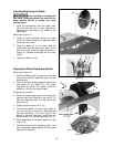
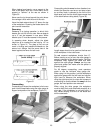
Calibrating the Rip Fence Scale
1. Attach the rip fence to the table (as described
in the previous section) to the right of the saw
blade, but do not lower the handle to clamp the
fence to the table.
2. Slide the fence against the saw blade.
You will need to raise the blade guard and the
anti-kick pawl to provide clearance for the
fence.
With the fence snug against the saw blade, clamp
the fence in position by lowering the handle. The
hairline on the indicator (A) should line up with 0"
on the rail (C). If they do not line up:
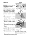
3. With a 12mm wrench, slightly loosen the six
hex nuts that secure the front rail (F) to the
table (C) and extension wings.
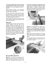
4. Adjust the position of the front rail so the red
hairline indicator (A, Fig. 17) on the fence scale
lines up with 0" (B, Fig. 18) on the rail.
Remember to keep the fence snug against the
saw blade.
Figure 16
Figure 17
Figure 18
5. When alignment is complete, tighten the six
hex nuts securing the front rail.