


8
Assembly
Stand Assembly
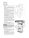
Referring to Figure 1:
1. Remove all contents from the shipping
container.
2. Clean all rust protected surfaces with a mild
solvent. Do not use paint or lacquer thinner,
gasoline, or mineral spirits; these will damage
painted surfaces.
3. Attach the four rubber pads (A) to the bottoms
of the side panels (C) with four each
5/16” x 5/8” screws, 5/16” flat washers and
5/16” hex nuts (B). The hardware can be found
in the bag with the rubber pads.
4. Attach the side panels (C) to the front panel (D)
with four 5/16” x 5/8” hex cap screws, eight
5/16” flat washers, four 5/16” lock washers, and
four 5/16” hex nuts (E). Hand tighten the
hardware at this point.
Note: Assemble the stand upside down to
make sure that the tops of the panels are flush.
5. Mount the shelf (F) to the inside of the stand
with two M5x10 pan head screws, two M5 flat
washers and two M5 lock washers (G).
6. Finish the stand assembly by attaching the rear
panel (H) to side panels (C) with four
5/16” x 5/8” hex cap screws, eight 5/16” flat
washers, four 5/16” lock washers, and four
5/16” hex nuts (J).
7. Make sure stand is sitting evenly on a level
surface before tightening hardware.
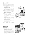
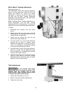
Installing Table and Motor Unit to Stand
The Table and Motor Unit is
heavy! Use great care and adequate resources
when lifting the unit up onto the stand! Failure
to comply may cause serious injury and/or
damage to the sander and/or property!
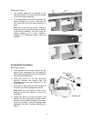
Referring to Figure 2:
1. With the aid of another person, carefully lift the
table and motor unit (A) out of the shipping
box, and up onto the stand (B).
2. Line up threaded holes in the base (C) with the
holes in the stand (D).
3. Open the cabinet door (E) and through the
opening attach main unit to stand with two
5/16” x 1-1/4” hex cap screws (F), two 5/16”
lock washers (G) and two 5/16” flat
washers (H). Tighten with a 12mm wrench.
Figure 1
Figure 2