


10
Electrical
Power Connection
Do not operate this
machine in damp
locations.
A separate electrical circuit should be used for
your machines. This circuit should not be less
than #12 wire and should be protected with a
20 Amp time lag fuse. If an extension cord is
used, use only 3-wire extension cords which
have 3-prong grounding type plugs and
matching receptacle, which will accept the
machine’s plug. Before connecting the machine
to the power line, make sure the switch is in the
Off position and be sure that the electric current
is of the same characteristics as indicated on
the machine. All line connections should make
good contact. Running on low voltage will
damage the machine.
Grounding Instructions
This machine must be
grounded while in use to
protect the user from shock
In the event of a malfunction or breakdown,
grounding provides a path of least resistance
for electric current to reduce the risk of electric
shock.
If you are not sure whether your outlet is
properly grounded, consult a qualified
electrician.
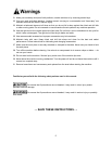
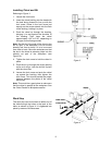
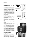
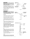
Referring to Figure 5: As received from the
factory, your mortiser is ready to run at 115-volt
operation. This mortiser is intended for use on
a circuit that has an outlet and a plug that looks
like the one illustrated in (A). A temporary
adaptor, which looks like the adaptor shown in
(B), may be used to connect this plug to a two-
pole receptacle if a properly grounded outlet is
not available. The temporary adaptor should
only be used until a properly grounded outlet
can be installed by a qualified electrician. This
adaptor is not applicable in Canada. The green
colored rigid ear, lug, or tab, extending from the
adaptor, must be connected to a permanent
ground such as a properly grounded outlet box.
Operating Controls
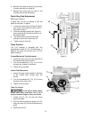
Start/Stop Switch
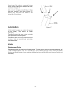
Referring to Figure 6: The Start/Stop Switch is
located to the left of the motor on the side of
the mortiser. To turn the mortiser on press the
green START (A) button. To stop the mortiser,
push the red STOP (B) button.
Figure 5
Figure 6