


8
Section 1: Assembly and Set-Up
DT55 & DTM55 Powered Ditchers 324-053M
3/17/08
Land Pride
Table of Contents
Section 1: Assembly and Set-Up
Tractor Requirements
This Powered Ditcher is designed with a Category 2 and
3, 3-point hitch. The maximum horsepower rating for the
tractor is 120 HP depending on lift capacity and field
conditions. Front tractor weights and/or ballast to tires
may be required to offset weight of unit. Consult your
tractor manual for details.
!
CAUTION
Your Ditcher must be mounted only on a tractor equipped with
a Category 2 or 3 hitch. Failure to do so may result in serious
injury.
Tractor Hook-Up
!
DANGER
Tractor hook-up to equipment is dangerous and can result in
serious injury or death. Do not allow anyone to stand between
the Powered Ditcher and tractor during hook-up operations.
Do not operate the hydraulic 3-point lift controls while
someone is directly behind the tractor or near the implement.
!
DANGER
Hydraulic fluid under pressure can penetrate skin. Wear
protective gloves and safety glasses or goggles when working
with hydraulic systems. Use a piece of cardboard or wood
rather than hands when searching for hydraulic leaks. If
hydraulic fluid is injected into the skin, it must be treated by a
doctor within a few hours or gangrene may result.
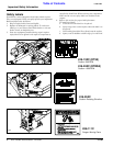
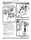
1. Slowly back tractor up to the Powered Ditcher while
using the tractor’s 3-point hydraulic control to align
the lower hitch link holes with the clevis lug holes on
the implement.
2. Engage tractor park brake, shut tractor engine off
and remove key before dismounting from tractor.
3. With tractor’s lower hitch arms aligned and
positioned in the clevises, attach the lower arms to
the clevises with hitch pins and secure with linch
pins.
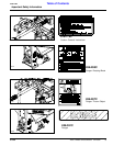
4. Connect top center link to the upper pivot hitch using
customer supplied clevis pin and linch pin.
5. Ensure that the lower hitch arms are blocked to
prevent excessive side movement.
6. Return to the tractor and slowly operate the 3-point
controls up and down to check for clearance between
the implement and tractor. Move or remove the
drawbar if it interferes with the Powered Ditcher.
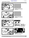
7. Manually adjust one of the two lower lift arms up or
down to level the Powered Ditcher from left to right.
Manually adjust the length of the top-link to level the
Powered Ditcher from front to rear.
Driveline Set-Up
If the Ditcher is to be used on more than one tractor, an
additional driveline may be required - especially if a quick
hitch is used.
!
CAUTION
Do not use a PTO adaptor with a quick hitch. A PTO adapter
will increase the strain on the tractor’s PTO shaft and can
damage the PTO shaft and tiller driveline.
!
WARNING
Damaged drivelines can cause serious injury or death.
!
CAUTION
Tractor PTO shield and all Ditcher guards must be in place at
all times during operation!
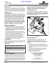
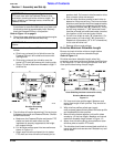
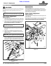
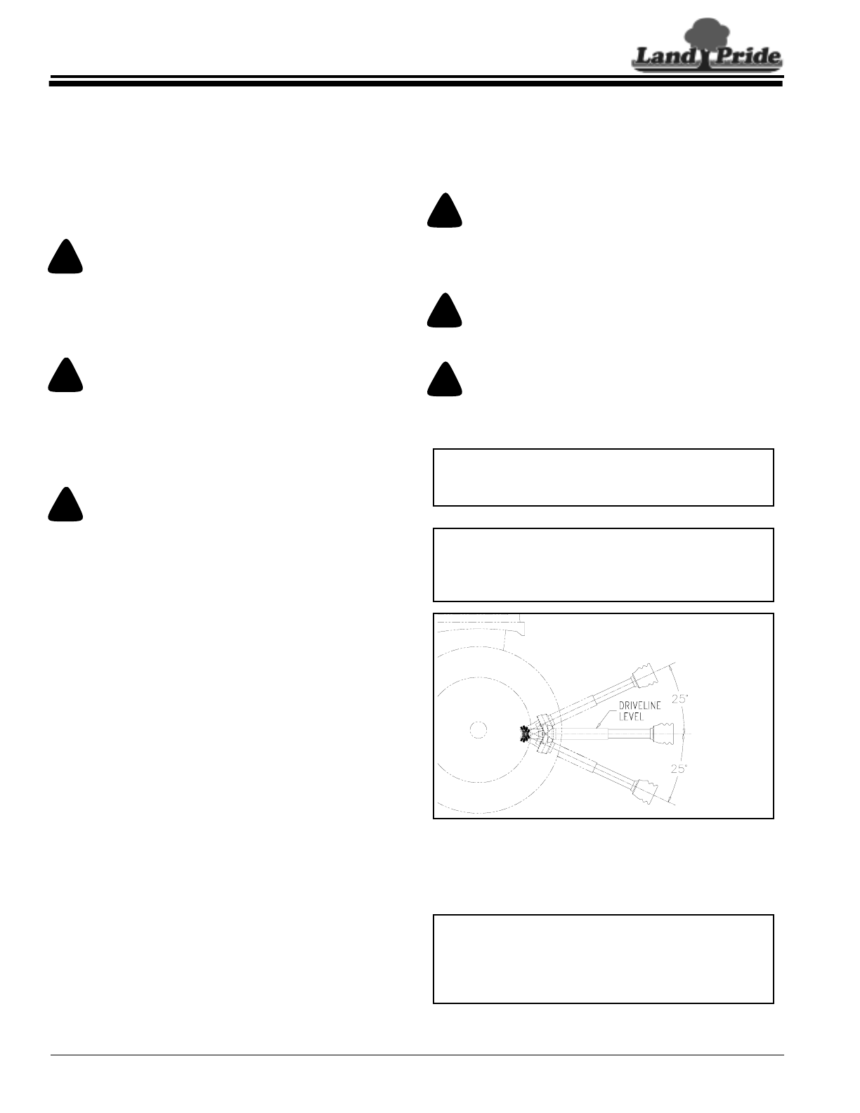
Maximum Allowable Driveline Movement
Figure 1-1
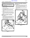
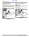
Checking Driveline Minimum Length
IMPORTANT: Some tractors are equipped with
multispeed PTO ranges. Be certain your tractor ‘s
PTO is set for the correct PTO speed.
IMPORTANT: Avoid premature driveline
breakdown. A driveline that is operating must not
exceed an angle of 25 degrees up or down while
operating the 3-point lift. See Figure 1-1 below.
24872
IMPORTANT: Always check driveline minimum
length and maximum allowable length during initial
setup and when connecting to a different tractor.
More than one driveline may be required to fit all
applications.