


11
Section 1: Assembly and Set-Up
3/17/08
DT55 & DTM55 Powered Ditchers 324-053M
Land Pride
Table of Contents
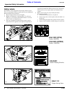
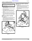
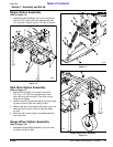
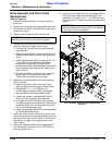
Ripper Option Assembly
Refer to Figure 1-6:
1. Assemble ripper Assembly (#1) to the main frame
with four 3/4” u-bolts (#2), lock washers (#3) and
3/4” nuts (#4). Tighten nuts to 170 ft-lbs. of torque.
Ripper Option Assembly
Figure 1-6
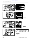
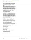
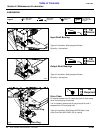
Skid Shoe Option Assembly
Refer to Figure 1-7:
1. Attach Skid Shoe (#1) to the main frame with
3/8”-16 x 1 1/4” GR5 round head square neck
bolt s (#2) and lock nuts (#3). Draw lock nuts up
snug, do not tighten.
2. Attach one end of turnbuckle (#5) to the main frame
lug with clevis pin (#6) and cotter pin (#4).
3. Attach other end of turnbuckle (#5) to the lug on the
skid shoe (#1) lug with clevis pin (#6) and cotter
pin (#4).
4. Bend one leg of each cotter pin to keep cotter pin
from falling out.
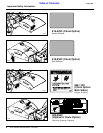
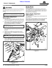
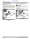
Gauge Wheel Option Assembly
Refer to Figure 1-8:
1. Assemble Gauge Wheel Assembly (#1) with hitch
pin (#2) and hair pin (#3).
20520
Skid Shoe Option Assembly
Figure 1-7
Gauge Wheel Option Assembly
Figure 1-8
25754
20519