


10
Section 1: Assembly and Set-Up
DT55 & DTM55 Powered Ditchers 324-053M
3/17/08
Land Pride
Table of Contents
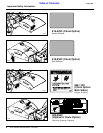
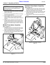
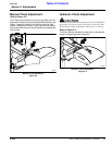
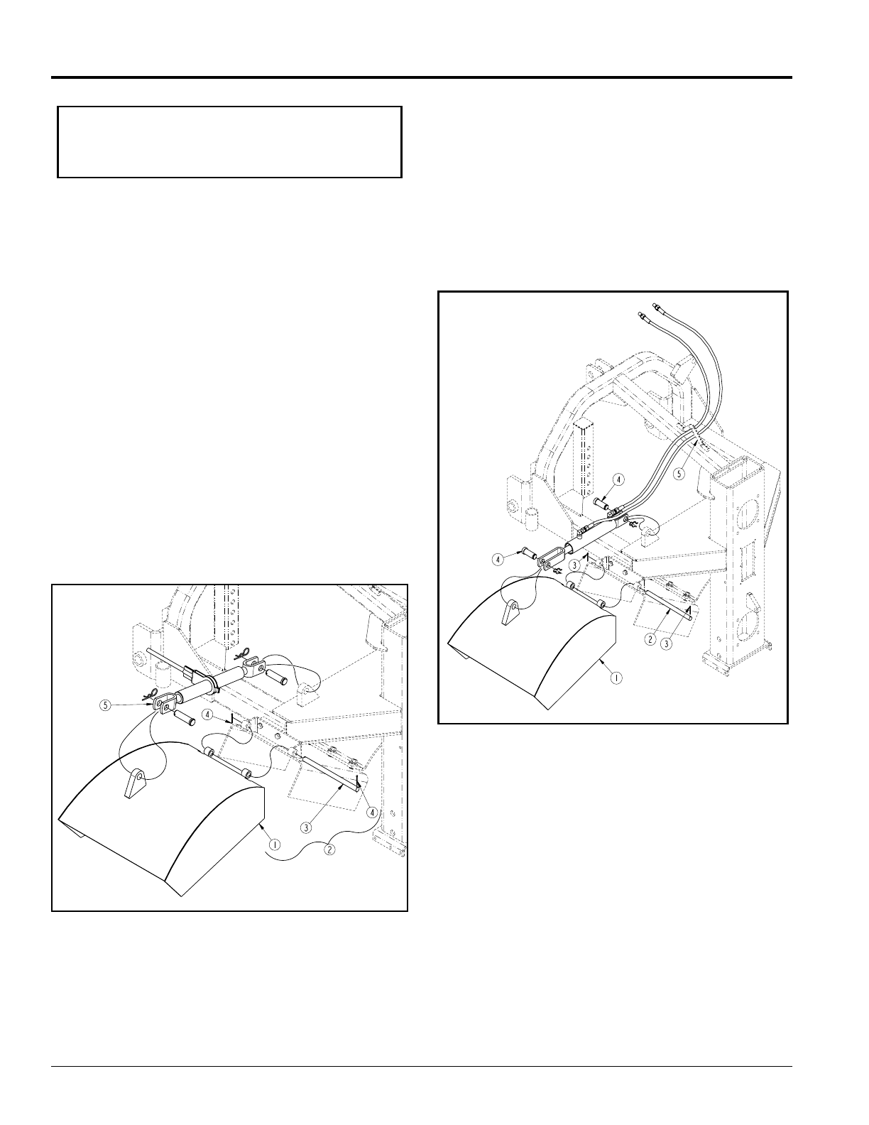
Hydraulic Chute Option Assembly
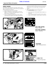
Refer to Figure 1-5:
1. Assemble Chute (#1) to the main frame with hinge
pin (#2) and cotter pins (#3). Bend one leg of each
cotter pin to keep cotter pin from falling out.
2. Attach hydraulic cylinder to the chute and frame lugs
as shown with clevis pins (#4). Secure clevis pins
with hair pin cotters.
3. Route hydraulic hoses through hose guide (#5) as
shown.
Hydraulic Chute Option Assembly
Figure 1-5
20522
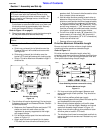
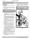
6. Hook driveline safety chain in the hole in the inner
driveline guard. Attach the other end to the Powered
Ditcher’s main frame.
7. Start tractor and raise Powered Ditcher just enough
to remove support blocks.
8. Slowly engage tractor’s 3-point controls to lower
Powered Ditcher. Check for sufficient drawbar
clearance. Move drawbar ahead, aside or remove if
required.
9. Raise and lower implement to find the maximum
possible extended driveline length. Check to make
certain that the driveline has not extended beyond
the maximum allowable length recorded in step 3 on
page 9.
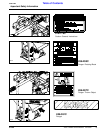
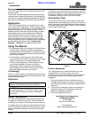
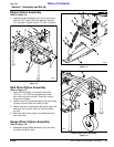
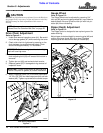
Manual Chute Option Assembly
Refer to Figure 1-4:
1. Assemble Chute (#1) to the main frame with hinge
pin (#3) and cotter pins (#4). Bend one leg of each
cotter pin to keep cotter pin from falling out.
2. Attach ratchet jack (#5) to the chute and frame lugs
as shown with clevis pins provided. Secure clevis
pins with hair pin cotters.
Manual Chute Option Assembly
Figure 1-4
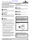
IMPORTANT: A small chain is supplied with the
driveline. This chain must be attached to the inner
driveline shield and to the Powered Ditcher to
restrict shield rotation.
20529