


14
Section 3: Adjustments
DT55 & DTM55 Powered Ditchers 324-053M
3/17/08
Land Pride
Table of Contents
Section 3: Adjustments
!
CAUTION
BEFORE any adjustments are performed, lower the Ditcher to
the ground slowly, stop tractor engine and remove switch key.
DO NOT attempt to make adjustments while tractor is
running.
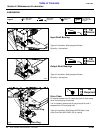
Drive Chain Adjustment
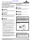
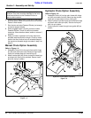
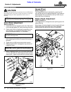
Refer to Figure 3-1:
1. Unbolt and remove inspection cover (#1). Be careful
not to damage gasket (#7) while removing the cover.
2. Check roller chain for tightness by pressing on the
chain between top and bottom sprockets. Chain
should have approximately 1/2” movement.
3. If the chain is loose, loosen jam nut (#5) and turn
chain adjusting bolt (#3) until excess chain slack is
removed.
4. Tighten jam nut (#5) and recheck chain tension.
5. Replace gasket (#7) if damaged during removal of
inspection cover.
6. Attach inspection cover (#1) to the main frame with
1/4”-20 x 5/8” GR5 hex head cap screw (#4) and lock
washer (#6). Tighten cap screw to the correct torque.
Idler Spring Adjustment
Figure 3-1
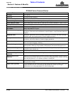
NOTE: For corrrect torque values, refer to “Torque
Values Chart For Common Bolt Size” on page 23.
IMPORTANT: Do Not over tighten drive chain. A tight
chain will have high wear.
IMPORTANT: Loctite is required on all bolts (#4) and
silicone is required on gasket (#7) before installation.
25755
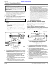
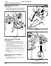
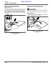
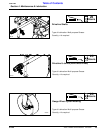
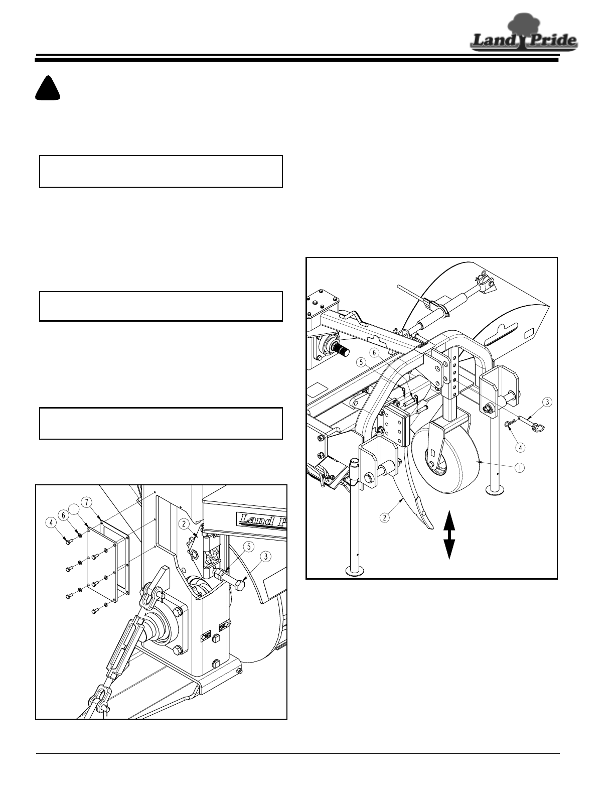
Gauge Wheel
Refer to Figure 3-2:
The Gauge Wheel can be adjusted by removing 3/4”
hitch pin (#3) and moving gauge wheel (#1) up or down to
desired depth. Be sure to secure hitch pin with hair pin
cotter (#4) when reinstalling.
Ripper Depth Adjustment
Refer to Figure 3-2:
The Ripper option is designed to tear up hard ground for
easier ditching.
Adjust ripper to desired depth by removing pins (#6) and
moving the ripper shank (#2) up or down. Replace
retaining pins and secure with hair pin cotters (#5).
Gauge Wheel Adjustment
Figure 3-2
25753