


9
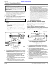
Section 1: Assembly and Set-Up
3/17/08
DT55 & DTM55 Powered Ditchers 324-053M
Land Pride
Table of Contents
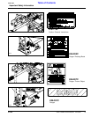
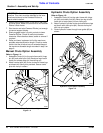
1. Start tractor and slowly engage tractor’s hydraulic
3-point lever to move the lower arms up or down until
the driveline shaft is approximately level. Securely
block the Powered Ditcher in this position.
Refer to Figure 1-2 on page 9:
2. Place tractor gear selector in park, shut tractor engine
off, set park brake and remove switch key.
3. Attach driveline to Powered Ditcher and tractor as
follows:
a. Slide inner universal joint of driveline over the
Powered Ditcher’s drive shaft and secure with
locking collar.
b. Slide outer universal joint driveline over the
tractor's PTO shaft and secure with locking collar.
c. Skip to "Driveline Maximum Allowable Length" if
driveline fits.
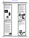
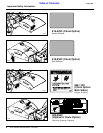
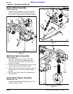
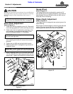
Driveline Shortening
Figure 1-2
4. The driveline will require shortening if it is too long to
fit between the tractor and Powered Ditcher. Shorten
driveline as follows:
a. Make sure the Powered Ditcher and tractor PTO
shafts are level with each other and the
implement is securely supported at this height
with support blocks.
b. Pull driveline profiles apart into two sections as
shown in Figure 1-2.
c. Attach outer driveline universal joint to tractor
PTO shaft and inner driveline universal joint to
IMPORTANT: It is necessary to align the tractor’s
PTO shaft level with the Powered Ditcher’s drive
shaft when checking driveline minimum length. Too
long a driveline can damage tractor, driveline and
Powered Ditcher.
IMPORTANT: The inner shield half attaches to the
Ditcher.
23758
gearbox shaft. Pull on each driveline section to be
sure universal joints are secured.
d. Hold driveline sections parallel to each other to
determine if they are too long. The inner and outer
shields on each section should endapproximately
1" short of reaching the universal joint shield on
the adjacent section (see “B” dimension). If they
are too long, measure 1" (“B” dimension) back
from the universal joint shield and make a mark at
this location on the inner and outer shields.
e. Cut off inner shield at mark (“X” dimension). Cut
same amount off inner shaft (“X1” dimension).
Repeat cut off procedure (“Y”&“Y1” dimensions)
to cut outer driveline half.
f. Remove all burrs and cuttings.
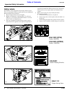
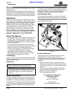
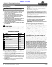
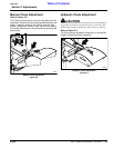
Driveline Maximum Allowable Length
Be sure to check driveline minimum length before
checking driveline maximum allowable length.
Refer to Figure 1-3:
Driveline maximum allowable length, when fully
extended, must have a minimum overlap of profile tubes
by not less than 1/2 the free length with both inner and
outer profile tubes being of equal length.
Driveline Maximum Length
Figure 1-3
1. Pull inner and outer profiles apart. Measure and
record free length of both profiles. They should be
the same.
2. With driveline profiles pulled apart, apply
multi-purpose grease to the inside of the outer profile
and reassemble the two profiles.
3. Move driveline halves together until profile tubes
overlap by 1/2 the free length. Measure and record
maximum allowable length shown in Figure 1-3.
4. Attach inner driveline yoke to drive shaft and outer
driveline yoke to tractor's PTO shaft.
5. The driveline should now be moved back and forth to
insure that both ends are secured. Reattach any end
that is loose.
24804
Outer Shielding has been removed for clarity.