


17
Section 4: Maintenance & Lubrication
3/17/08
DT55 & DTM55 Powered Ditchers 324-053M
Land Pride
Table of Contents
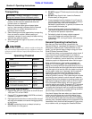
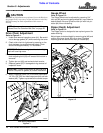
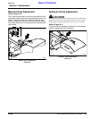
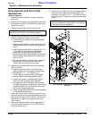
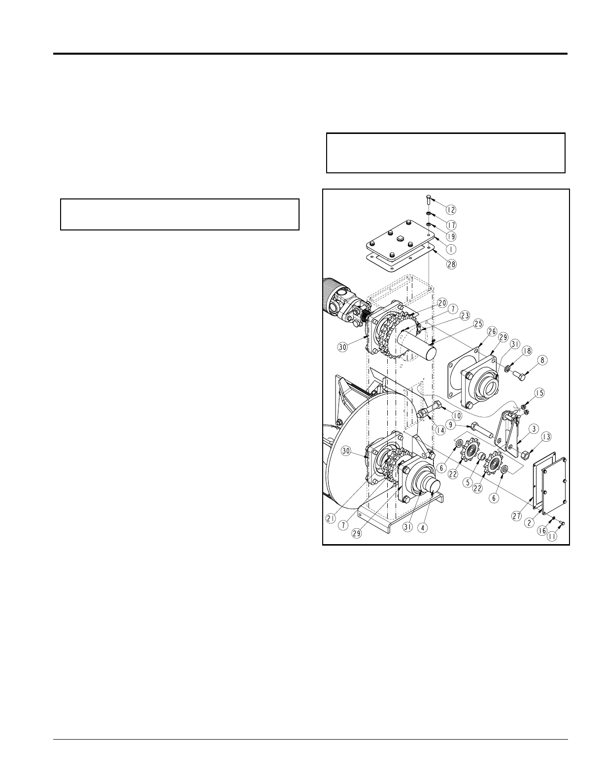
Drive Sprocket and Drive Chain
Replacement
Refer to Figure 4-1:
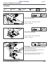
1. Remove top cover plate (#1) and rear inspection
plate (#2).
2. Loosen jam nut (#14) and idler adjustment bolt (#10).
3. Roll master link (#23) in dual #80 roller chain to top
center and remove.
4. Remove chain by pulling chain from the top.
5. Replace idler sprockets (#22) by removing tightener
assembly (#3) from inside the chain case.
a. Unscrew 3/8” nuts (#15) and remove tightener
assembly (#3).
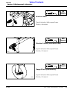
b. Remove cap screw (#9), spacers (#5 & #6) and
sprockets (#22). Keep cap screw and spacers for
reuse.
c. Install new sprockets (#22) by inserting 3/4”-10 x
3 1/2” GR5 hex head cap screw threw idler
bracket (#3), spacer (#6), sprocket (#22),
sprocket spacer (#5), sprocket (#22), spacer (#6)
and out through idler bracket (#3). Secure with
lock nut (#13).
d. Bolt idler assembly to inside of chain case with
existing 3/8”-16 hex flange lock nuts (#15).
Tighten 3/8” nuts to the correct torque.
6. Replace drive sprocket (#20) and driven sprocket
(#21) as follows:
a. Remove lock collars (#31) from rear flange
bearings (#29) and front flange bearings (#30).
b. Remove 5/8”-11 x 1 1/2” GR5 hex cap
screws (#8), lock washers (#18), rear flange
bearings (#29) and bearing gaskets (#26).
c. Loosen set screws in sprockets (#20 & #21).
There are 2 set screws for each sprocket.
d. Pull upper drive shaft (#25)and lower impeller
shaft (#4) towards front of implement while sliding
sprockets (#20 & #21) off the shafts. Be careful
not to loose woodruff keys (#7).
e. Install new sprockets (#20 & #21) and reassemble
by reversing above process.
7. Install new chain from the top by using a pull line or
wire to help guide chain around sprockets so you can
add master link at top center. Refer to “Drive Chain
Adjustment” on page 14 to properly adjust roller
chain tension.
8. Install rear inspection plate (#2) and gasket (#27)
with lock washer (#16) and 1/4”-2 x 5/8” GR5 hex
head cap screws (#11).
IMPORTANT: Loctite is required on all installed bolts
and silicone is required on all installed gaskets.
9. Install top cover plate (#1) and cover gasket (#28)
with galvanized rubber clad washers (#19), lock
washers (#17) and 3/8”-16 x 1 1/4” GR5 hex head
cap screws (#12). Tighten cap screws to the correct
torque.
Drive Sprocket and Drive Chain Replacement
Figure 4-1
IMPORTANT: Make sure not to forget to install 3/8”
galvanized rubber clad washers (#19). If not replaced
oil could leak out during operation.
20532