


The frame of the machine must be grounded. A
ground terminal marked with the symbol located at
the left side of the input box is provided for this pur-
pose. See the U.S. National Electrical Code for details
on proper grounding methods. Follow other grounding
instructions per the paragraph under “High Frequency
Interference Protection”.
On multiple voltage input machines, be
sure the
reconnect panel is connected per the following
instructions for the voltage being supplied to the
machine. See Figure 1 in the back of this manual.
• Failure to follow these instructions can cause imme-
diate failure of machine components.
------------------------------------------------------------------------
The PRO-CUT is shipped connected for the highest
nameplate input voltage. To change this connector
for a different input voltage, reconnect the power
straps to their respective terminals corresponding to
the input voltage used.
Fuse the input circuit with the recommended super lag
fuses. Choose an input and grounding wire size
according to local codes or use the Input Connection
table. “Delay type”
(1)
circuit breakers may be used in
place of fuses. Using fuses or circuit breakers smaller
than recommended may result in “nuisance” tripping
from machine inrush currents even if not cutting or
gouging at high currents.
(1)
Also called “inverse time” or “thermal/magnetic” circuit breakers; circuit
breakers which have a delay in tripping action that decreases as the magni-
tude of the current increases.
AIR INPUT CONNECTIONS
A source of clean compressed air or nitrogen must be
supplied to the PRO-CUT. The supply pressure must
be between 70 and 120 psi (482 and 827 kPa). The
flow rate is approximately 4.7 cfm (133 l/min). Oil in
the air is a very severe problem and must be avoided.
Remove the plastic thread protector from the regulator
input port (located on the back of the machine). Use a
suitable gas connection fitting to make the connection
to the available air supply. The input port is a 1/4”
(6.3 mm) NPT thread. Tighten the air fitting to prevent
leakage but do not overtighten. The use of Teflon
tape to seal the connection is recommended.
Nitrogen from cylinders may be used with this
machine. The cylinder of nitrogen gas must be
equipped with a pressure regulator. No more than
120 psi (827 kPa) may be supplied to the regulator on
the machine. Install a hose between the regulator on
the gas cylinder and the gas inlet on the machine.
OUTPUT CONNECTIONS
Torch Connection
The PRO-CUT comes factory equipped with a cutting
torch.
Pictures of the torch along with the required replace-
ment parts are shown in the parts lists in the back of
this manual. The ends of the cable to be connected to
the power source are unique. Follow the applicable
instructions as given in Figure 2 in the back of this
manual.
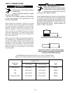
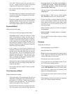
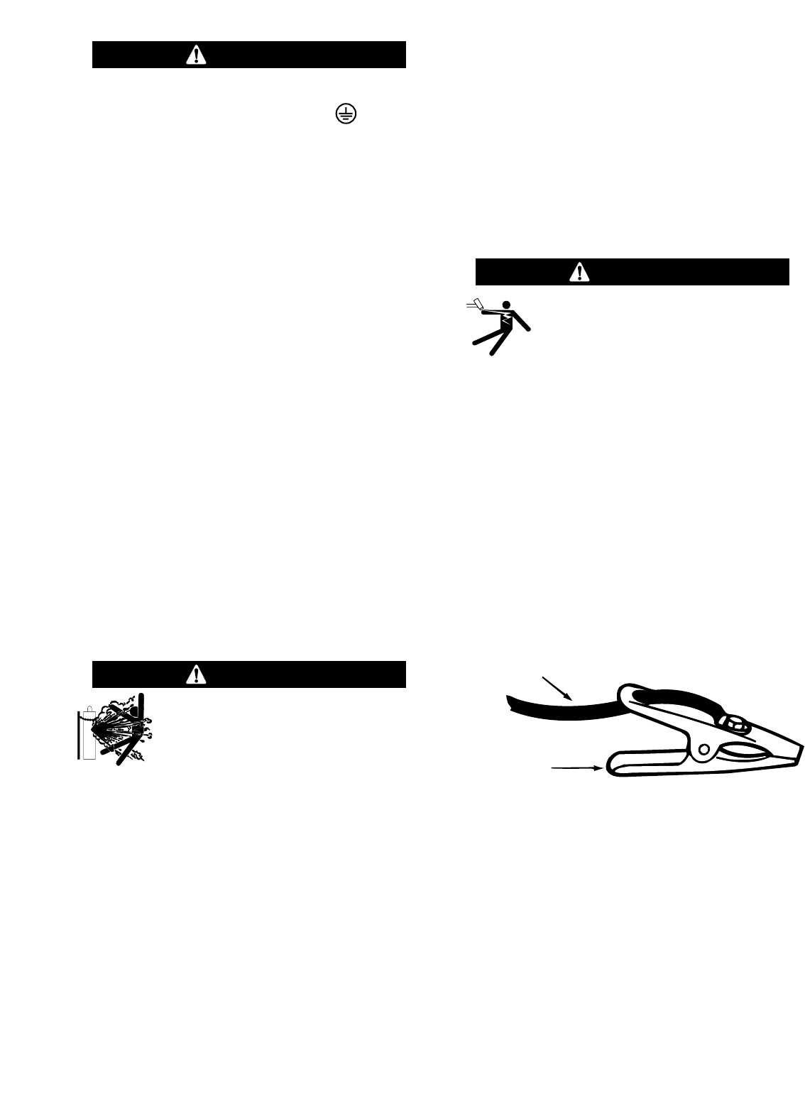
Work Cable and Clamp Installation
Attach the work clamp to the work cable (which
extends from the front of the machine) as shown.
Tighten nut and bolt securely.
OPERATING INSTRUCTIONS
Sequence of events:
A. Turn on the line power.
B. Connect the air supply to the machine.
C. Turn the power switch on.
-The green “Power On” LED should begin to
glow.
– 11 –
HIGH FREQUENCY SHOCK CAN
CAUSE INJURY OR FALL.
• Keep the cutting torch and cables in
good condition.
•
Secure yourself in position to avoid a fall.
----------------------------------------------------------------------------
WARNING
CAUTION
Work cable
Work clamp
CYLINDER may explode if damaged
• Keep cylinder upright and chained to a
fixed support.
• Keep cylinder away from areas where it
may be damaged.
• Never lift equipment with cylinder attached.
• Never allow the cutting torch to touch cylinder.
• Keep cylinder away from live electrical circuits.
• Maximum inlet pressure 120 psig (827 kPa).
------------------------------------------------------------------------
WARNING