


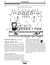
WELDER CONTROLS (Items 9 through 13 )
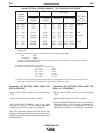
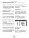
9. WELD MODE & OUTPUT CONTROL
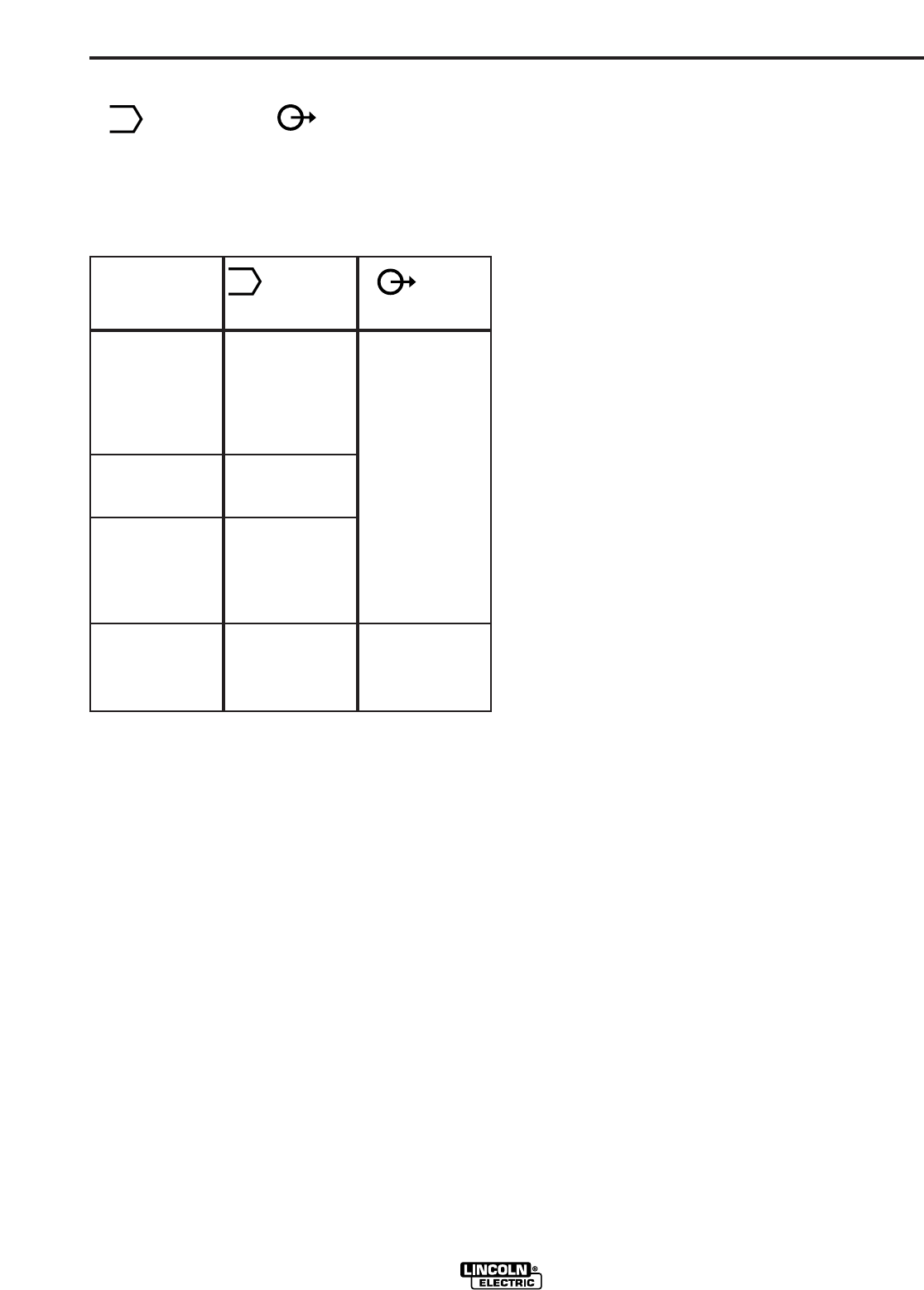
These two controls allow you to select between various
welding output slopes and adjust the desired welding
output. Refer to Table B.1 for a description of how
these two controls work.
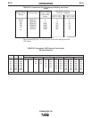
Table B.1 Weld Mode and Output Control
Functions
1
If the WELD MODE switch is positioned between settings the pre-
vious setting is maintained until the switch is properly positioned on
a setting.
2
OUTPUT also controls O.C.V. while in the 5 sloped output ranges.
10. DIGITAL OUTPUT METERS
The digital output meters are located in the center of
the control panel between the two large control knobs.
The digital meters allow the output voltage (CV-WIRE
mode) or current (CC-STICK, PIPE and TIG modes) to
be set prior to welding using the OUTPUT control dial.
During welding, the meter display the actual output
voltage (VOLTS) and current (AMPS). A memory fea-
ture holds the display of both meters on the seven sec-
onds after welding is stopped. This allows the operator
to read the actual current and voltage just prior to when
welding was ceased. While the display is being held
the left-most decimal point in each display will be flash-
ing. The accuracy of the meters is + or - 3%.
11. WELDING TERMINALS SWITCH
The toggle switch on the control panel labeled “Weld
Terminals On” and “Remotely Controlled”: is used to
control the operation of the “solid state contactor”
which allows for the selection of “Hot” or “Cold” weld-
B-5
OPERATION
B-5
ing terminals.
With the switch in the “Weld Terminals On” position the
contactor is closed and the welding terminals are
always “Hot”.
With the switch in the “Remotely Controlled” position
the contactor operation is controlled by an Amptrol, Arc
Start Switch or some other type of triggering device
through the use of a control cable connected to the 14-
pin MS connector.
When the triggering device is pressed the contactor is
closed and the welding terminals are “Hot”.
When the triggering device is released the contactor is
opened and the welding terminals are “Cold”.
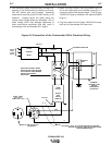
NOTE: The new Chopper Technology control circuitry
automatically senses when a remote output control pot
is plugged into either amphenol. Therefore, there is no
need for a local / remote switch.
12. 6 - PIN CONNECTOR
For attaching optional remote control equipment.
When in the CC-STICK, PIPE, and CV-WIRE modes
and when a remote control is connected to the
Amphenol, the auto-sensing circuit automatically
switches the OUTPUT control from control at the
welder to remote control .
When using the TOUCH START TIG mode with a TIG
Module connected, the OUTPUT control is used to set
the maximum current range of the CURRENT CON-
TROL on the TIG Module.
13. WELD OUTPUT TERMINALS + AND -
These 1/2 - 13 studs with flange nuts provide welding
connection points for the electrode and work cables.
For positive polarity welding the electrode cable con-
nects to the “+” terminal and the work cable connects
to this “-” terminal. For negative polarity welding the
work cable connects to the “+” terminal and the elec-
trode cable connects to this “-” terminal.
AUXILIARY POWER CONTROLS
(Items 14 - 17)
14. 120/240VAC RECEPTACLE
This is a 120/240VAC (14-50R) receptacle that pro-
vides 240VAC or can be split for 120VAC single phase
auxiliary power. This receptacle has a 50 amp rating.
Refer to the AUXILIARY POWER RECEPTACLES
section in the installation chapter for further information
about this receptacle. Also refer to the AUXILIARY
POWER OPERATION section later in this chapter.
COMMANDER 500
M
Sloped Output for
Pipe Welding.
Touch Start TIG
Welding
Constant Current
Output for
Fabrication and
General Purpose
Welding
Constant Voltage
Output for MIG
Wire or CORED
WIRE Welding
5 Range
Settings
90, 150, 200,
350, 500 (Max.
current on each
setting)
1 Range setting
20-250 Amps
1 Range setting
30-575 Amps
1 Range setting
14 to 40 Volts
Provides a fine
adjustment of
welding current
from
Min (1) to Max
(10) within each
range
Provides Fine
Voltage
Adjustment
Weld Mode
1
Application
Output
2
M