


B-6
OPERATION
B-6
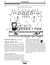
15. CIRCUIT BREAKERS
These circuit breakers provide separate overload cur-
rent protection for each 120V circuit at the 240V recep-
tacle, each 120V receptacle, the 120VAC in the 14-Pin
connector, the 42VAC in the 14-Pin connector and (for
codes above 10838 only) battery circuit overload pro-
tection.
16. 120VAC RECEPTACLES
These two 120VAC (5-20R) receptacles provide
120VAC for auxiliary power. Each receptacle has a 20
amp total rating. Refer to the AUXILIARY POWER
RECEPTACLES section in the installation chapter for
further information about these receptacles. Also refer
to the AUXILIARY POWER OPERATION section later
in this chapter.
17. GROUND STUD
Provides a connection point for connecting the
machine case to earth ground for the safest grounding
procedure. Refer to “MACHINE GROUNDING” in the
Installation chapter for proper machine grounding infor-
mation.
18. VOLTMETER +/- SWITCH
Changes the polarity display on the wire feeder.
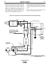
19. 14 - PIN CONNECTOR
For attaching wire feeder control cable. Includes con-
tactor closure circuit, auto-sensing remote control cir-
cuit, and 120V and 42V power. The remote control cir-
cuit operates the same as the 6 Pin Amphenol.
20. ARC CONTROL
The ARC CONTROL WIRE/STICK dial is active in the
WIRE and STICK modes, and has different functions in
these modes. This control is not active in the TIG and
PIPE modes.
CC-STICK mode: In this mode, the ARC CONTROL
knob sets the short circuit current during stick welding
(arc-force). Increasing the number from -10 to +10
increases the short circuit current and prevents stick-
ing of the electrode to the plate while welding. This can
also increase spatter. It is recommended that the ARC
CONTROL be set to the minimum number without
electrode sticking. Start with a setting at 0.
CV-WIRE mode: In this mode, turning the ARC CON-
TROL clockwise from –10 (soft) to +10 (crisp) changes
the arc from soft and washed-in to crisp and narrow. It
acts as an inductance control. The proper setting
depends on the procedure and operator preference.
Start with a setting at 0.
ENGINE OPERATION
STARTING THE ENGINE
1. Open the engine compartment door and check that
the fuel shutoff valve located to the left of the fuel fil-
ter housing is in the open position (lever to be in line
with the hose).
2. Check for proper oil level on the oil dipstick. Close
engine compartment door.
3. Remove all plugs connected to the AC power receptacles.
4. Set IDLER switch to “AUTO”.
5. Set the RUN/STOP switch to “RUN”. Observe that all
engine protection lights momentarily turn on, some lights
may turn off before starting. Check the fuel gauge
(K1639-2 only for codes 10838 and below)
to make
sure that there is an adequate fuel level.
6. Press and hold the engine START button for a minimum
of 2 seconds.
7. Release the engine START button when the engine
starts.
8.
Check that the indicator lights are off. If the LOW FUEL light
is on (K1639-2 only
for codes 10838 and below
), the
engine will shutdown 30 minutes after starting. If any other
indicator light is on after starting, the engine will shutdown in a
few seconds. Investigate any indicated problem.
9. Allow the engine to warm up at low idle speed for several
minutes before applying a load and/or switching to high
idle. Allow a longer warm up time in cold weather.
COLD WEATHER STARTING
With a fully charged battery and the proper weight oil,
the engine should start satisfactorily even down to
about 0°F. If the engine must be frequently started
below 10°F, it may be desirable to install the optional
ether starter kit (K825-1). Installation and operating
instructions are included in the kit.
STOPPING THE ENGINE
1. Switch the RUN/STOP switch to “STOP”. This turns
off the voltage supplied to the shutdown solenoid.
A backup shutdown can be accomplished by shut-
ting off the fuel valve located on the fuel line.
COMMANDER 500