


B-9
OPERATION
B-9
WIRE FEED (CONSTANT VOLTAGE) WELD-
ING
Connect a wire feeder to the Commander 500 and set
welder controls according to the instructions listed earlier
in this section.
The Commander 500 in the ”CV-WIRE” position, permits it
to be used with a broad range of flux cored wire
(Innershield and Outershield) electrodes and solid wires
for MIG welding (gas metal arc welding). Welding can be
finely tuned using the “ARC CONTROL”.
Some recommended Innershield electrodes are: NR-311,
NS-3M, NR-207, NR-203 Ni 1%, NR-204-H.
Recommended Outershield electrodes are: 0S-70, 0S-
71M.
Some recommended solid wires for MIG welding are:
.035 (0.9 mm), .045 (1.1 mm) and .052 (1.3 mm), L-50
and L-56, .035 (0.9 mm) and .045 (1.1 mm) Blue Max MIG
308 LS.
For any electrodes, including the above recommenda-
tions, the procedures should be kept within the rating of
the machine. For additional electrode information, see
Lincoln publications N-675, GS-100 and GS-210.
AUXILIARY POWER OPERATION
Start the engine and set the IDLER control switch to
the desired operating mode. Full power is available
regardless of the welding control settings, if no welding
current is being drawn.
The auxiliary power of the Commander consists of two
20 Amp-120VAC (5-20R) duplex receptacles and one
50 Amp-120/240 VAC (14-50R) receptacle. The
120/240VAC receptacle can be split for single phase
120 VAC operation.
The auxiliary power capacity is 12,000 watts of 60 Hz,
single phase power. The auxiliary power capacity rat-
ing in watts is equivalent to volt-amperes at unity
power factor. The maximum permissible current of the
240 VAC output is 50 A. The 240 VAC output can be
split to provide two separate 120 VAC outputs with a
maximum permissible current of 50 A per output to two
separate 120 VAC branch circuits. Output voltage is
within ± 10% at all loads up to rated capacity.
NOTE: The 120/240V receptacle has two 120V out-
puts of different phases and cannot be paralleled.
The auxiliary power receptacles should only be used
with three wire grounded type plugs or approved dou-
ble insulated tools with two wire plugs.
The current rating of any plug used with the system
must be at least equal to the current capacity of the
associated receptacle.
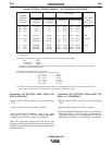
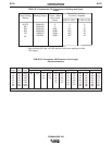
SIMULTANEOUS WELDING AND AUXIL-
IARY POWER LOADS
It must be noted that the above auxiliary power ratings
are with no welding load. Simultaneous welding and
power loads are specified in table B.4. The permissi-
ble currents shown assume that current is being drawn
from either the 120 VAC or 240 VAC supply (not both
at the same time).
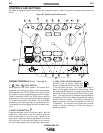
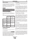
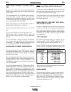
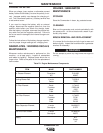
ARC GOUGING
For optimal performance when arc gouging, set the
Commander 500’s “WELD MODE” switch to the “CC -
STICK” position, and the “ARC CONTROL” to 10.
Set the “OUTPUT” knob to adjust output current to the
desired level for the gouging electrode being used
according to the ratings in the following table:
* Maximum current setting is limited to the Commander
500’s maximum of 575 Amps.
PARALLELING
When paralleling machines in order to combine their
outputs, all units must be operated in th CC - STICK
mode only. To achieve this turn the WELD MODE
switch to the CC - STICK position. Operation in other
modes may produce erratic outputs, and large output
imbalances between the units.
COMMANDER 500
ELECTRODE CURRENT RANGE
DIAMETER (DC,electrode positive)
1/8” 60-90 Amps
5/32” 90-150 Amps
3/16” 200-250 Amps
1/4 300 Amps
5/16” 350-450 Amps
3/8” 450 Amps*