


B-8
OPERATION
B-8
Commander 500 SETTINGS WHEN USING THE
K799 HI-FREQ UNIT
• Set the WELD MODE switch to the “20-250 setting”
(TIG)
•. Set the IDLER switch to the “HIGH “ position.
• Set the WELDING TERMINALS switch to the “Weld
Terminals On” position. This will close the solid state
contactor and provide an always “hot” electrode.
(Note: This is necessary because the K799 circuitry with
respect to the #2 and #4 leads does not provide the prop-
er signal to open and close the solid state contactor in the
Commander 500).
Commander 500 SETTINGS WHEN USING THE
K930-1 or -2 TIG MODULE
• Set the WELD MODE switch to the 20-250 Setting
(TIG).
• Set the IDLER switch to the “AUTO “ position.
• Set the WELDING TERMINALS switch to the “Remotely
Controlled” position. This will keep the solid state con-
tactor open and provide a “cold” electrode until the trig-
gering device (Amptrol or Arc Start Switch) is pressed.
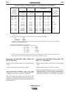
COMMANDER 500
Tungsten
Electrode
Diameter
in. (mm)
2-15
5-20
15-80
70-150
150-250
250-400
400-500
500-750
750-1000
(3)
(3)
(3)
10-20
15-30
25-40
40-55
55-80
80-125
3-8 (2-4)
5-10 (3-5)
5-10 (3-5)
5-10 (3-5)
13-17 (6-8)
15-23 (7-11)
21-25 (10-12)
23-27 (11-13)
28-32 (13-15)
3-8 (2-4)
5-10 (3-5)
5-10 (3-5)
9-13 (4-6)
11-15 (5-7)
11-15 (5-7)
13-17 (6-8)
18-22 (8-10)
23-27 (11-13)
TIG TORCH
Nozzle
Size (4), (5)
Approximate Argon Gas Flow Rate
C.F.H. (l/min.)
DCEN (-) DCEP (+)
#4, #5, #6
#5, #6
#6, #7, #8
#8, #10
0 .010 (.25)
0.020 (.50)
0.040 (1.0)
1/16 (1.6)
3/32 (2.4)
1/8 (3.2)
5/32 (4.0)
3/16 (4.8)
1/4 (6.4)
1%, 2%
Thoriated
Tungsten
1%, 2%
Thoriated
Tungsten
Aluminum Stainless Steel
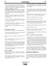
Table B.3 TYPICAL CURRENT RANGES
(1)
FOR TUNGSTEN ELECTRODES
(2)
(1) When used with argon gas. The current ranges shown must be reduced when using argon/helium or pure helium
shielding gases.
(2) Tungsten electrodes are classified as follows by the American Welding Society (AWS):
Pure EWP
1% Thoriated EWTh-1
2% Thoriated EWTh-2
Though not yet recognized by the AWS, Ceriated Tungsten is now widely accepted as a substitute for 2% Thoriated
Tungsten in AC and DC applications.
(3) DCEP is not commonly used in these sizes.
(4) TIG torch nozzle “sizes” are in multiples of 1/16ths of an inch:
# 4 = 1/4 in. (6 mm)
# 5 = 5/16 in. (8 mm)
# 6 = 3/8 in. (10 mm)
# 7 = 7/16 in. (11 mm)
# 8 = 1/2 in. (12.5 mm)
#10 = 5/8 in. (16 mm)
(5) TIG torch nozzles are typically made from alumina ceramic. Special applications may require lava nozzles, which are
less prone to breakage, but cannot withstand high temperatures and high duty cycles.