


B-1
INSTALLATION
B-1
INSTALLATION
HAVE QUALIFIED PERSONNEL DO THE INSTAL-
LATION WORK. TURN THE ENGINE OFF BEFORE
WORKING INSIDE THE MACHINE. IN SOME
CASES IT MAY BE NECESSARY TO REMOVE
SAFETY GUARDS TO PERFORM REQUIRED
INSTALLATION. REMOVE GUARDS ONLY WHEN
NECESSARY AND REPLACE THEM WHEN THE
INSTALLATION REQUIRING THEIR REMOVAL IS
COMPLETE. ALWAYS USE THE GREATEST CARE
WHEN WORKING NEAR MOVING PARTS.
LN-15, LN-22, LN-25 Connection — Instructions cov-
ered under “Operation”.
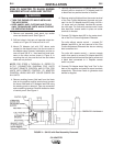
LN-7 Connection — An LN-7 can be connected to SA-
250, SAE-300, SAE-350, SAE-400 and SAE-400
WELD’N AIR engine welders that have AC auxiliary
power by using a K240 Contactor Kit. Connect the con-
tactor kit to the engine welder and LN-7 per S17525 or
S15416 connection diagram that is sent with the K240
Contactor Kit. The engine welder 115 volt receptacle
will supply the AC power that is needed. Place the
welder idler control in the high position before welding.
When the LN-7 is connected to an SA-250 or SAE-350,
it will not run at low idle when the idle control is in the
automatic position. The plug connecting the K240
Contactor Kit to the SA-250 or SAE-350 auxiliary
power receptacle must be disconnected to allow the
engine to run at low idle.
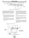
ANY SPEED UP OF THE ENGINE RPM BY
CHANGING THE GOVERNOR SETTING OR OVER-
RIDING THE THROTTLE LINKAGE WILL CAUSE
AN INCREASE IN THE AC AUXILIARY VOLTAGE.
IF THIS VOLTAGE GOES ABOVE 140 VOLTS, THE
LN-7 CONTROL CIRCUIT AND/OR THE CV
ADAPTER CIRCUIT WILL BE DAMAGED! THE
ENGINE GOVERNOR SETTING IS PRESET AT THE
FACTORY — DO NOT ADJUST ABOVE RPM
SPECIFICATIONS LISTED IN ENGINE WELDER
OPERATING MANUAL.
The following tools and materials are recommended for
attaching the CV Adapter to an engine welder:
1. Measuring tape, hammer, center punch and electric
drill with 13/32" drill bit. This is only needed for SA-
250 engine welders that do not have mounting
holes in fuel tank rail.
2. Set of socket wrenches.
3. 11/32" wrench and 3/8" nut driver or pliers.
4. 1/2" open end wrench and 9/16" wrench.
5. Screwdriver.
6. Electrical insulating tape.
K384 CV ADAPTER TO SA-200 ENGINE
WELDER
NOTE: BEFORE INSTALLING CV ADAPTER, START
ENGINE WELDER AND USE A DC VOLTMETER TO
CHECK THE POLARITY OF THE RED AND BLACK
LEADS CONNECTED TO THE AUXILIARY POWER
RECEPTACLE. THE RED LEAD SHOULD BE NEGA-
TIVE AND THE BLACK LEAD SHOULD BE POSI-
TIVE. IF THE POLARITY IS NOT CORRECT, REFER
TO ENGINE WELDER OPERATING MANUAL FOR
INSTRUCTIONS TO FLASH THE EXCITER TO
OBTAIN THE CORRECT POLARITY.
• TURN THE ENGINE OFF WHILE INSTALLING
THIS ACCESSORY.
• KEEP HANDS, HAIR, CLOTHING AND TOOLS
AWAY FROM MOVING PARTS WHEN STARTING
OR OPERATING ENGINE.
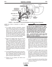
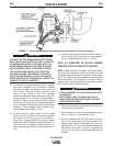
1. Remove roof assembly and bracket cover (cover
on top and at rear of generator). (See Figure 2.)
Also, remove the two gas tank support mounting
bolts on the side opposite the output studs.
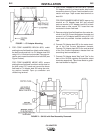
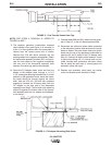
2. Mount CV Adapter (nameplate should have an
“SA” above the code number) to the gas tank sup-
port holes. Use one 3/8" bolt with hardware
removed in Step 1 and one stud on Adapter. One
3/8" bolt will not be used as a 3/8" stud from the
Adapter case replaces it. In mounting the unit, be
sure the fuel line and choke cable are not pinched.
(See Figure 1.)
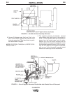
NOTE: FOR STEPS 3 THROUGH 10, REFER TO
S17514 OR S17515 CONNECTION DIAGRAMS FOR
THE APPROPRIATE WELDER CODE NUMBER. CV
ADAPTER CONTROL LEADS ARE NOT COLOR
CODED ON ALL UNITS.
CV ADAPTER
WARNING
CAUTION
WARNING