


E-6
DIAGRAMS
E-6
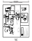
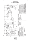
CV ADAPTER
-
+
CV ADAPTOR CONTROL LEADS
U
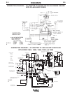
ELECTRICAL SYMBOLS
U
E
A
2
F
1
N
U
AC
W
ARE NOT COLOR CODED
LEAD 613 DOES NOT APPEAR
ON CV ADAPTOR UNITS BELOW 8785
*
R
ON ALL UNITS
Y
FLASHING DIODE
W
PER E1537
AC
U
TO ALTERNATOR
N
Y
(-)
B
N
TO ENGINE CIRCUIT
COPPER TERMINAL
TO WORK / POSITIVE
CV & VV OUTPUT TERMINAL
NEGATIVE CV OUTPUT TERMINAL
(+)
B
W
R
TO NEGATIVE BRUSH HOLDER
VV OUTPUT TERMINAL
ELECTRODE / NEGATIVE
RHEOSTAT
JOB SELECTOR
500
Y
120
CURRENT CONTROL
REACTOR
(REVERSING SWITCH)
POLARITY SWITCH
W
600
611
610
W
612W
U
B
REMOTE CONTROL
(SWITCH SHOWN IN
LEAD COLOR CODE
G
602
25
509
503
U-BLUE
Y-YELLOW
25
YBY
R-RED
W-WHITE
N-BROWN
G-GREEN
B-BLACK
POS.
W
G
RECEPTACLE FOR
REMOTE CONTROL
RHEOSTAT
CB1
GROUND TERMINAL
WIDE SLOT
TO ALTERNATOR
LOCAL POSITION)
*
G
25
RESISTORS
R
613
NEG.
CV ADAPTER
CB2
G
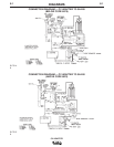
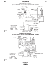
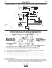
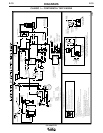
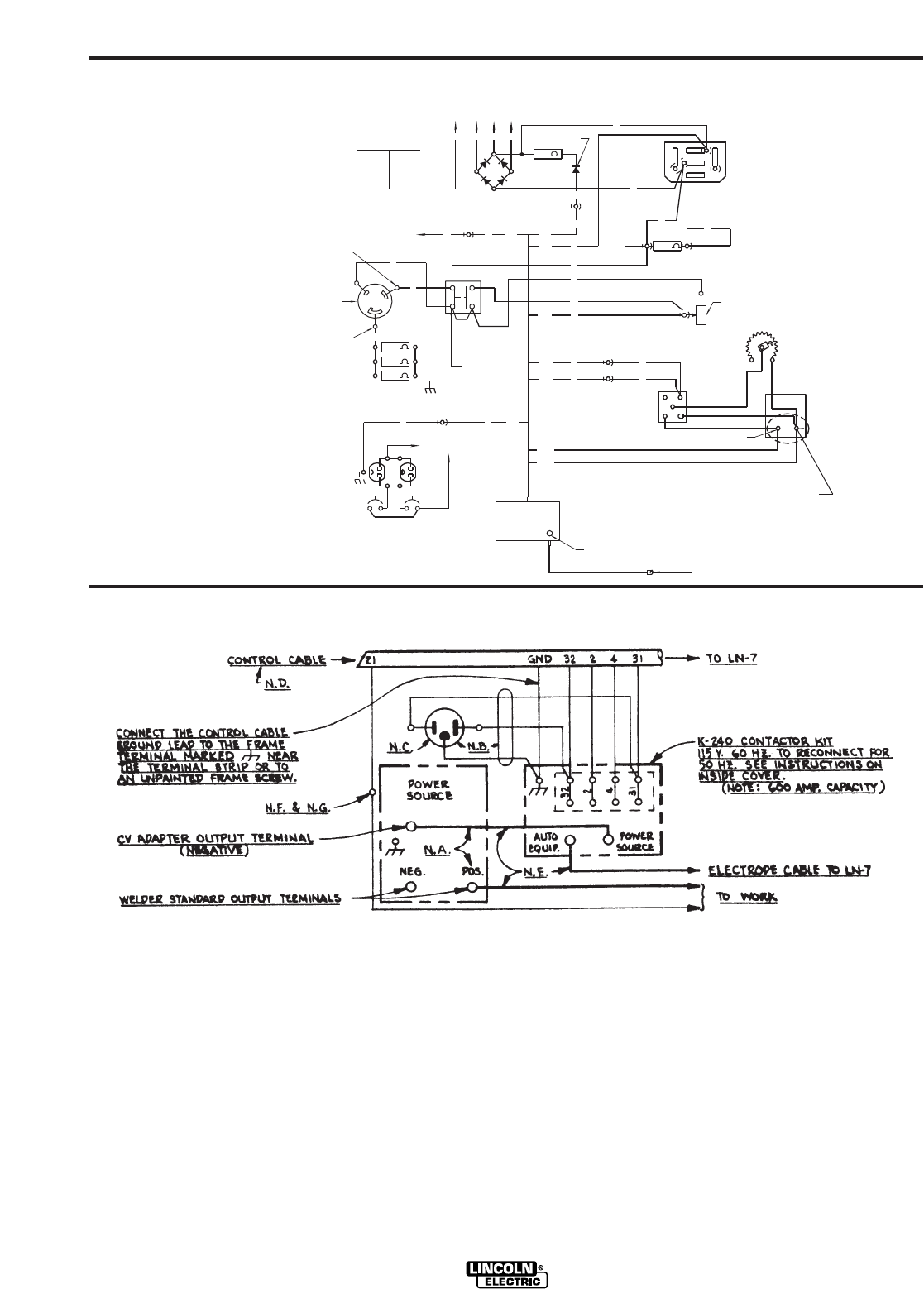
CONNECTION DIAGRAM —
CV ADAPTER TO SAE-400 AND WELD’N AIR ENGINE WELDER Code 10362 AND 10665
S24466
B.01
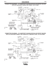
N.A. Connection shown for negative polarity. For positive polarity, reverse cables connected to output terminals.
N.B. 3 conductor #16 power cord physically suitable for the installation and plug rated at 115 volts 15 amperes AC.
N.C. Plug into 115 volt AC receptacle on welder control panel or other 115 volt AC supply rated a minimum of 500 volt amperes.
N.D. Leads #21 and GND. do not appear on LN-7’s with codes below 7026.
N.E. Welding cables must be of proper capacity for the current and duty cycle on immediate and future applications.
N.F. If LN-7 is equipped with a meter kit, extend lead 21 using #14 or larger insulated wire physically suitable for the installation. An
S16586-[ ] remote voltage sensing work lead is available for this purpose. Connect it directly to the work piece keeping it electrically
separate from the welding work lead circuit and connection. For convenience, this extended #21 lead should be taped to the welding
work lead.
N.G. Tape up bolted connection.
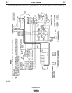
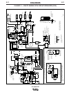
CAUTION: Any speed up of the engine RPM by changing the governor setting or over-riding the throttle linkage will cause an increase in
the AC auxiliary voltage. If this voltage goes above 140 volts, the LN-7 control circuit will be damaged. The engine governor set-
ting is pre-set at the factory — do not adjust above RPM specifications listed in engine welder operating manual.
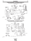
CONNECTION DIAGRAM — LN-7 WIRE FEEDER TO ENGINE WELDERS WITH
115 VOLT AC AUXILIARY POWER, CV ADAPTER AND K240 CONTACTOR KIT
S17525
7-15-83