


B-14
INSTALLATION
CV ADAPTER
B-14
9. Connect CV Adapter lead 610 to same terminal on
polarity switch that is connected to existing black
lead.
10.
• (For SAE-300 and -400 welders with DC auxil-
iary power) Use tape to separately insulate CV
Adapter leads 611, 612 and 613. These leads are
not used.
• (For SAE-300 and -400 welders with AC auxil-
iary power between Codes 7160 and 8812)
Disconnect the flashing diode lead from the flash-
ing contactor solenoid. The flashing diode and the
flashing contactor solenoid are mounted on the
side of the reactor box located behind the control
panel. Connect CV Adapter lead 611 to diode lead
removed from flashing contactor solenoid using
#10 x 1/4 screw and nut provided. Insulate connec-
tion with tape. Connect CV Adapter lead 612 to
flashing contactor solenoid terminal that was con-
nected to flashing diode lead. Insulate lead 613
with tape.
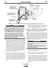
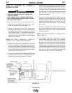
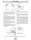
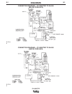
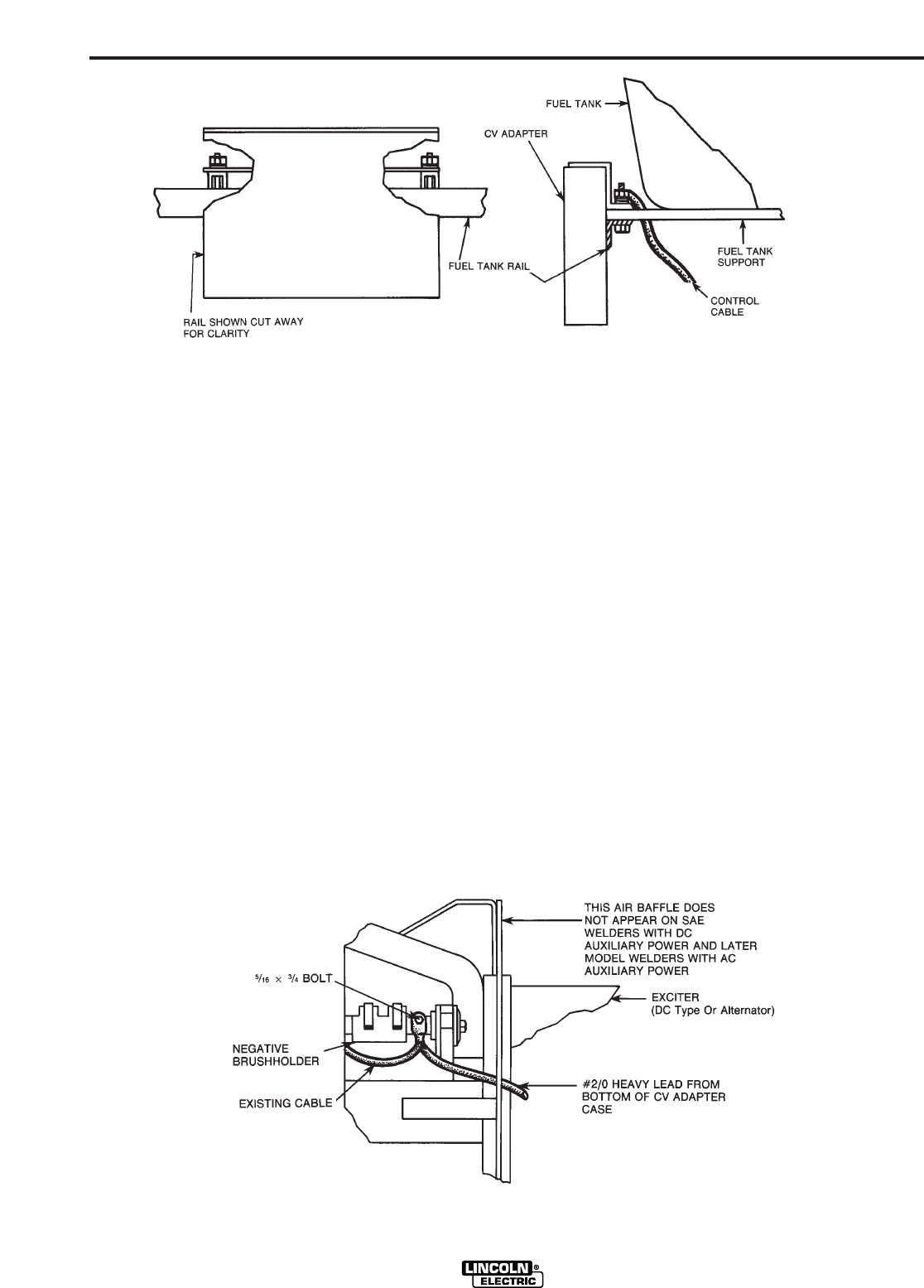
FIGURE 13 – Frame Rail Mounting.
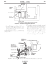
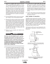
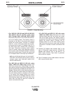
FIGURE 14 – View of Negative Generator Brushholder after Bracket cover is Removed.
7.
• (For code 8812 through 10400
, 10549
and
10664, 10665) Route CV Adapter leads 600, 602,
610, 612 and 613 through plastic lead clamp on
Current Control reactor housing. Connect CV
Adapter lead 602 to the center terminal of the Job
Selector rheostat.
• (For SAE 400 and WELD N’ AIR with codes
10601, 10602, 10856, 10884 AND 10885) Route
the CV Adapter leads 600, 602, 610, 612 and 613
through the plastic lead clamp on the side of the
“Current Control” reactor box. Connect the CV
Adapter leads 600 and 602 to the 500Ω resistor
with the exiting yellow lead.
8.
• (For Code 8812 through 10400
, 10549
and
10664) Connect the CV Adapter lead 600 to the
end terminal of the Job Selector rheostat that has
an existing lead connected to it.
• (For SAE 400 and WELD N’ AIR with codes
10362 and 10665) Connect the CV Adapter lead
600 to the resistor terminal with two existing yellow
leads connected to it.