


B-16
INSTALLATION
CV ADAPTER
B-16
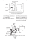
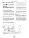
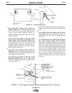
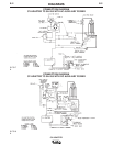
NOTE: FOR STEPS 13 AND 14 REFER TO FIGURES 12 AND 14.
13. The negative generator brushholder, exposed
when upper bracket cover or wrap-around is
removed (see Figure 12), is at the 11 o’clock posi-
tion when the commutator is viewed from the con-
trol panel end of welder. Remove the 5/16 bolt
which connects the existing cable to the negative
brushholder. Route the #2/0 heavy lead which
exists from the bottom of the CV adapter case as
shown in Figure 14. Obtain a 5/16 X 3/4 bolt from
the hardware sent with the CV Adapter and con-
nect the #2/0 heavy lead which exits from the bot-
tom of the CV Adapter case, along with the cable
removed above, to the negative brushholder. The
#2/0 heavy lead lug should be between the exist-
ing cable lug and the brushholder. Tape the #2/0
heavy lead to the battery lead on welders with DC
auxiliary power to support lead. On welders with
AC auxiliary power, tape the #2/0 heavy lead to the
alternator exciter lead bundle coming from the
alternator to support lead where possible.
14. Replace bracket cover removed in Step 1. Also,
tighten the K385-1 CV Adapter which was loosely
mounted in Step 2. For the SAE-400 WELD’N AIR
the CV Adapter must be positioned flush against
the fuel tank rail after tightening.
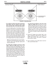
15. Peel backing from decals sent in mounting kit
package and install as shown in Figure 15. On the
(SAE-400 codes 10601, 10856 and 10884) and all
WELD’N AIR reinstall the two guards that were
removed at step 1. Be sure that the guards have a
clearance of at least one half inch from any electri-
cally live part. All new and existing leads must be
routed so they are clear of any sharp edges on the
guards.
POLARITY OF THE STANDARD OUTPUT TERMINALS MUST BE AS
STATED IN STEP 16 AND THE MAXIMUM OPEN CIRCUIT VOLTAGE
WITH THE LOWER MODE SWITCH IN CV POSITION MUST BE AS STAT-
ED IN STEP 17 BEFORE PLACING THE UPPER MODE SWITCH IN CV
POSITION. FAILURE TO HAVE THE CORRECT POLARITY AND VOLT-
AGE BEFORE PLACING THE UPPER MODE SWITCH IN CV POSITION
WILL RESULT IN DAMAGE TO THE CV ADAPTER.
--------------------------------------------------------------------------------------------------
16. To check the VV output, place both CV/VV switch-
es on the CV Adapter in the “VV” position. Set the
Remote Control Switch to the “REMOTE” or
“LOCAL” position as applicable, if so equipped.
Start the engine welder and set for full speed oper-
ation. Use a DC voltmeter to check the output
polarity. The “Electrode” output terminal that is
relabeled “Negative” must be negative and the “To
Work” output terminal that is relabeled “Positive”
must be positive. If polarity is not correct, recheck
Steps 3 to 12. Voltage should be about 40-60 volts
DC when the “Job Selector” control is set at mini-
mum and 90-100 volts DC when set at maximum.
These voltages may be higher if readings are
taken when welder is cold.
17. To check the CV output, place only the lower CV
Adapter switch in the CV position. This may be
done while the engine is running as long as no
welding is being done. On codes 10600 and
above the “Job Selector” must be at Maximum
.
Check voltage between the output stud on the CV
adapter and frame ground. The voltage should be
less than 10 VDC. Voltage between the “To Work”
output terminal that is relabeled “Positive” and the
CV Adapter output terminal should be 7-12 volts
DC when the CV Adapter voltage control is at min-
imum setting and 36-48 volts DC at maximum set-
ting.
18. If output varies greatly from that specified in Steps
16 and 17, check wiring and refer to the trou
bleshooting section of the manual.
CAUTION