


B-3
INSTALLATION
B-3
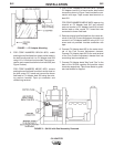
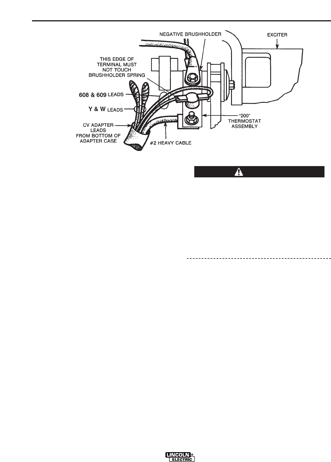
NOTE: FOR STEPS 8 THROUGH 10, REFER TO
FIGURE 3.
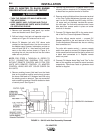
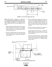
8. The negative generator brushholder, exposed
when bracket cover (see Figure 2) is removed, is
at the 11 o’clock position when the commutator is
viewed from the control panel end of welder.
Remove the 5/16 bolt which connects the two
existing cables to the negative brushholder. Locate
the thermostat assembly marked “200” and recon-
nect the two cables to the negative brushholder
with one end of the thermostat assembly bolted
between the cable lugs and the brushholder.
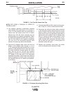
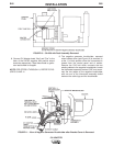
9. Route the CV Adapter leads, which exit from the
bottom of the Adapter case, through a 1-1/4 x
3-1/2" rectangular opening located at the 5 o’clock
position on the generator frame. Inside the frame,
the leads should be formed against the frame
shell. Use the 5/16-18 x 5/8 bolt with hardware
supplied to connect the #2 heavy cable from the
CV Adapter to the free end of the thermostat
assembly from Step 8. The flat side of the cable lug
should be against the bottom side of the thermo-
stat assembly with the nut washer and lockwasher
on the top.
10. Connect leads 608 and 609, routed into the gener-
ator in Step 9, to the two thermostat terminals. Use
tape to separately insulate the unused Y and W
leads. Insure that all leads are well clear of moving
parts and secured in place with tape.
11. Replace the roof assembly and bracket cover
removed in Step 1.
POLARITY OF THE STANDARD OUTPUT TERMI-
NALS MUST BE AS STATED IN STEP 12 AND THE
MAXIMUM OPEN CIRCUIT VOLTAGE WITH THE
LOWER MODE SWITCH IN CV POSITION MUST
BE AS STATED IN STEP 13 BEFORE PLACING
THE UPPER MODE SWITCH IN CV POSITION.
FAILURE TO HAVE THE CORRECT POLARITY
AND VOLTAGE BEFORE PLACING THE UPPER
MODE SWITCH IN CV POSITION WILL RESULT IN
DAMAGE TO THE CV ADAPTER.
12. To check the VV output, place both CV/VV switch-
es on the CV Adapter in the “VV” position. Start the
SA-200 and place idler control in “high” position.
Use a DC voltmeter across the standard output ter-
minals to check the output polarity. If it is incorrect,
recheck Steps 3 through 10. Voltage should be
about 47-60 volts DC when the Fine Current
Adjustment is set at minimum and 87-100 volts DC
when set at maximum. These voltages may be
slightly higher if readings are taken when welder is
cold.
13. To check the CV output, place only the lower
switch in the “CV” position. This may be done while
the engine is running as long as no welding is
being done. Voltage between the positive output
terminal and the CV output terminal should be 7-12
volts DC when the CV Adapter voltage control is at
minimum setting and 36-48 volts DC at maximum
setting.
14. If output varies greatly from that specified in Steps
12 and 13, check wiring and refer to troubleshoot-
ing section of manual.
CV ADAPTER
CAUTION
FIGURE 3 – View of Negative Generator Brushholder after Bracket Cover is Removed.