


B-4
INSTALLATION
B-4
K384 CV ADAPTER TO SA-250 ENGINE
WELDER WITH AC AUXILIARY OUTPUT
• TURN THE ENGINE OFF WHILE INSTALLING
THIS ACCESSORY.
• KEEP HANDS, HAIR, CLOTHING AND TOOLS
AWAY FROM MOVING PARTS WHEN STARTING
OR OPERATING ENGINE.
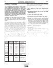
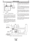
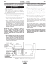
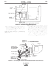
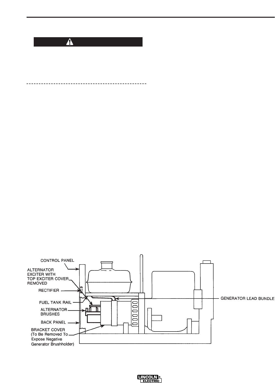
1. Remove roof assembly, back panel, top exciter
cover and bracket cover. See Figure 4.
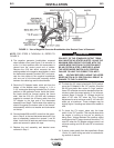
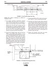
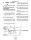
2. Drill two holes in fuel tank rail opposite output ter-
minals as in Figure 2 if holes are not in unit.
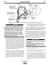
3. Mount CV Adapter (unit with “SA” above code
number) to the support holes. Use the one stud on
the Adapter case, a spacer, lockwasher, and nut on
one end and 3/8-16 x 1 hex head bolt and hard-
ware on the other end as shown in Figure 6. In
mounting the unit, be sure the fuel line and choke
cable are not pinched.
NOTE: FOR STEPS 4 THROUGH 12, REFER TO
S17517 CONNECTION DIAGRAM FOR UNITS
WITHOUT REMOTE CONTROL AND S17766 FOR
UNITS WITH REMOTE CONTROL. CV ADAPTER
CONTROL LEADS ARE NOT COLOR CODED ON
ALL UNITS.
4. Remove existing brown field lead from the black
lead on the positive rectifier terminal and connect
the brown field lead to CV Adapter lead 509 using
the existing push-on terminal. Tape up connection
and unused ring terminal. Rectifier located on back
of control panel. See Figure 4.
5. Tape up ring terminal on CV Adapter lead 610 and
connect push-on terminal of CV Adapter lead 610
to black lead on positive terminal of rectifier.
6. Remove existing field lead from the center terminal
of the Fine Current Adjustment rheostat and con-
nect it to the CV Adapter lead 503 using #10-24 x
1/4 screw and nut provided. Insulate the connec-
tion with tape. For units with remote control, leave
blue lead from remote switch in place on center
terminal of rheostat.
7. Connect CV Adapter lead 602 to the center termi-
nal of the Fine Current Adjustment Rheostat.
For units without remote control — connect CV
Adapter lead 600 to the end terminal of the Fine
Current Adjustment Rheostat that has an existing
lead connected to it.
For units with remote control — remove remote
switch from panel to connect CV Adapter lead 600
to the remote switch terminal that has a yellow and
a black lead connected to it. Replace remote
switch on panel.
8. Connect CV Adapter leads “Neg” and “Pos” to the
back of the negative and positive output terminals
respectively. Tape these leads to generator lead
bundle for support.
CV ADAPTER
WARNING
FIGURE 4 – SA-250 with Roof Assembly Removed.