


– 10 –
INSTALLATION
4. Keep the torch in good repair and all connections
tight to reduce high frequency leakage.
5. The work terminal must be connected to a ground
within ten feet of the welder, using one of the
following methods:
a) A metal underground water pipe in direct
contact with the earth for ten feet or more.
b) A 3/4” (19mm) galvanized pipe or a 5/8”
(16mm) solid galvanized iron, steel or copper
rod driven at least eight feet into the ground.
The ground should be securely made and the
grounding cable should be as short as possible
using cable of the same size as the work cable, or
larger. Grounding to the building frame electrical
conduit or a long pipe system can result in re-
radiation, effectively making these members
radiating antennas.
6. Keep all access panels and covers securely in
place.
7. All electrical conductors within 50 ft (15.2m) of the
welder should be enclosed in grounded rigid
metallic conduit or equivalent shielding. Flexible
metallic conduit is generally not suitable.
8. When the welder is enclosed in a metal building,
several good earth driven electrical grounds (as in
5 (b) above) around the periphery of the building
are recommended.
Failure to observe these recommended installation
procedures can cause radio or TV interference
problems and result in unsatisfactory welding
performance resulting from lost high frequency
power.
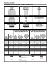
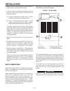
See Figure 1 for the location of the rating plate, the
entry hole, and the reconnect panel.
FIGURE 1 - REAR PANEL
1. RATING PLATE 3. 220V RECEPTACLE & BREAKER
2. INPUT ENTRY & (50/60 HZ MACHINE ONLY)
RECONNECT PANEL 4. 115V RECEPTACLE & BREAKER
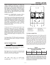
Have a qualified electrician connect the input leads to
L1 and L2 of the input panel in accordance with all
local codes and national electrical codes, and the
connection diagram located on the inside of the cover.
Use a single phase line or one phase of a two or three
phase line.
On multiple input voltage welders, be sure the
reconnect panel is connected per the following
instructions for the voltage being supplied to the
welder.
Failure to follow these instructions can cause
immediate failure of components within the welder.
___________________________________________
INPUT CONNECTIONS
Be sure the voltage, phase, and frequency of the input
power is as specified on the rating plate, located on
the rear of the machine.
Welder supply line entry provision is in the case rear
panel with a removable cover over the input
connection panel area. Entry is through a 1.7 in
(43mm) diameter hole in the case back. European
machines have a plastic bushing good for 3 - 10mm
2
conductors. For larger input conductors a customer
supplied plastic bushing should be used if required by
local or national code specifications.
1
4
3
2
CAUTION