


– 21 –
OPERATION
7. If welding with AC polarity, select Auto Balance™.
This gives the optimum ratio between cleaning and
penetration, automatically adjusted for the output
current. If manual adjustment of the AC Wave
Balance is desired, select Manual Balance, and
adjust the wave balance with the Cleaning and
Penetration keys. See the Advanced Features
section for more information on setting and using
the AC Wave Balance.
8. Select TIG Pulser On or Off. If the TIG Pulser is
on, adjust the pulse frequency with the Pulses Per
Second Up/Down keys. See the Advanced
Features section for more information on setting
and using the TIG Pulser.
9. Set the Afterflow time with the Seconds Up/Down
keys. Afterflow time provides shielding gas flow
(and cooling water, if used) after the weld. Use
short Afterflow times with low currents and small
tungstens, use long afterflow times at high output
currents with large tungstens.
TIG WELDING SEQUENCE OF OPERATION
(2-STEP MODE)
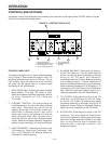
1. Connect an Arc Start Switch or an Amptrol to the
Remote Receptacle.
2.
Turn on the welder, gas supply and water supply (if
so
equipped). The Control Panel Display and
red LEDS will illuminate when the power is on.
3. Select the TIG 2-Step Weld Mode.
4. Select Local (if using an Arc Start Switch) or
Remote (if using an Amptrol) current control. Set
the output current using the Amps Up/Down keys.
The output current setting will be displayed on the
Ammeter.
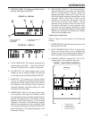
5. Select Continuous High Frequency if welding with
AC polarity, or Start Only High Frequency if
welding with DC- polarity. High Frequency Off can
be used for scratch start welding.
6. Select AC or DC- electrode polarity. See Table 2.
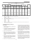
.010 (.25)
0.020 (.50)
0.040 (1.0)
1/16 (1.6)
3/32 (2.4)
1/8 (3.2)
5/32 (4.0)
3/16 (4.8)
1/4 (6.4)
2-15
5-20
15-80
70-150
150-250
250-400
400-500
500-750
750-1000
(3)
(3)
(3)
10-20
15-30
25-40
40-55
55-80
80-125
2-15
5-15
10-60
50-100
100-160
150-210
200-275
250-350
325-450
2-15
5-20
15-80
70-150
140-235
225-325
300-400
400-500
500-630
2-15
10-20
20-30
30-80
60-130
100-180
100-240
190-300
250-400
---
5-20
20-60
60-120
100-180
160-250
200-320
290-390
340-525
3-8 (2-4)
5-10 (3-5)
5-10 (3-5)
5-10 (3-5)
13-17 (6-8)
15-23 (7-11)
21-25 (10-12)
23-27 (11-13)
28-32 (13-15)
3-8 (2-4)
5-10 (3-5)
5-10 (3-5)
9-13 (4-6)
11-15 (5-7)
11-15 (5-7)
13-17 (6-8)
18-22 (8-10)
23-27(11-13)
#4, #5, #6
#5, #6
#6, #7, #8
#8, #10
1%, 2%
Thoriated
Tungsten
1%, 2%
Thoriated
Tungsten
Pure
Tungsten
1%, 2%
Thoriated
Tungsten
Zirconiated
Pure
Tungsten
1%, 2%
Thoriated
Tungsten
Zirconiated Aluminum
Stainless
Steel
Tungsten
Electrode
Diameter
in. (mm)
TIG Torch
Nozzle
Size
(4)
,
(5)
DCEN (
-
) DCEP (
+
)
Unbalanced Wave Balanced Wave
AC Approximate Argon
Gas Flow Rate
C.F.H. (1/min.)
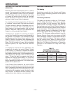
(1) When used with argon gas. The current ranges shown must be reduced when using argon/helium or pure helium shielding gasses.
(2) Tungsten electrodes are classified as follows by the American Welding Society (AWS):
Pure . . . . . . . . . . . . . . . EWP
1% Thoriated . . . . . . . . EWTh-1
2% Thoriated . . . . . . . . EWTh-2
Though not yet recognized by the AWS, Ceriated Tungsten is now widely accepted as a substitute for 2% Thoriated Tungsten in AC and DC applications.
(3) DCEP is not commonly used in these sizes.
(4) TIG torch nozzle “sizes” are in multiples of 1/16ths of an inch:
#4 = 1/4 in. (6 mm)
#5 = 5/16 in. (8 mm)
#6 = 3/8 in. (10 mm)
#7 = 7/16 in. (11 mm)
#8 = 1/2 in. (12.5 mm)
#10 = 5/8 in. (16 mm)
(5) TIG torch nozzles are typically made from alumina ceramic. Special applications may require lava nozzles, which are less prone to breakage, but cannot
withstand high temperatures and high duty cycles.
TABLE 3
TYPICAL CURRENT RANGES
(1)
FOR TUNGSTEN ELECTRODES
(2)