


– 9 –
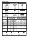
INSTALLATION
Read entire installation section before starting
installation.
Safety Precautions
SELECT SUITABLE LOCATION
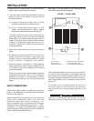
Place the welder where clean cooling air can freely
circulate in through the rear louvers and out through
the side louvers. Dirt, dust or any foreign material that
can be drawn into the welder should be kept at a
minimum. Failure to observe these precautions can
result in excessive operating temperatures and
nuisance shut-downs.
STACKING
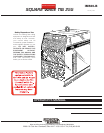
Square Wave TIG 255’s cannot be stacked.
TILTING
Each machine must be placed on a secure, level
surface, either directly or on a recommended
undercarriage. The machine may topple over if this
procedure is not followed.
ENVIRONMENTAL PROTECTION
Square Wave TIG 255 power sources carry an IP21
protection rating. They are rated for use in rain-
sheltered environments.
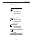
ELECTRIC SHOCK can kill.
• Only qualified personnel should
perform this installation.
• Turn the input power OFF at the
disconnect switch or fuse box
before working on this
equipment.
• Do not touch electrically hot
parts.
• Always connect the Square Wave
TIG 255 grounding terminal
(located on the bottom of the
input connection box) to a good
electrical earth ground.
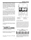
MACHINE GROUNDING AND HIGH
FREQUENCY INTERFERENCE
PROTECTION
The frame of the welder must be grounded. A ground
terminal marked with the symbol is located at
the bottom of the input box for this purpose. See your
local and national electrical codes for proper
grounding methods.
The spark gap oscillator in the high frequency
generator, being similar to a radio transmitter, can be
blamed for many radio, TV and electronic equipment
interference problems. These problems may be the
result of radiated interference. Proper grounding
methods can reduce or eliminate radiated
interference.
Radiated interference can develop in the following
four ways:
1. Direct interference radiated from the welder.
2. Direct interference radiated from the welding leads.
3. Direct interference radiated from feedback into the
power lines.
4. Interference from re-radiation of “pickup” by
ungrounded metallic objects.
Keeping these contributing factors in mind, installing
equipment per the following instructions should
minimize problems.
1. Keep the welder power supply lines as short as
possible and completely enclose them in rigid
metallic conduit or equivalent shielding for a
minimum distance of 50 feet (15.2m). There
should be good electrical contact between this
conduit and the welder. Both ends of the conduit
should be connected to a driven ground and the
entire length should be continuous.
2. Keep the work and electrode leads as short as
possible and as close together as possible.
Lengths should not exceed 25 ft (7.6m). Tape the
leads together when practical.
3. Be sure the torch and work cable rubber coverings
are free of cuts and cracks that allow high
frequency leakage. Cables with high natural
rubber content, such as Lincoln Stable-Arc® better
resist high frequency leakage than neoprene and
other synthetic rubber insulated cables.
WARNING