


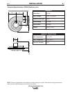

"##
""##!(
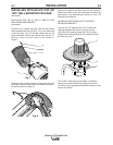
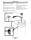
Mount the hanging adapter (Fig. 5D) to the hinge rod
(Fig. 5C) using (2) 1.75” bolts with washers and nuts.
Mount the spring bracket (Fig. 5F) into the two holes
as shown. Position one 8” rubber seal (Fig. 5A) on the
red plastic ring. Roll the bottom half up and slide the
connecting hose (Fig. 5E) over the bottom of the red
plastic ring. Roll the bottom of the rubber seal down
over the end of the connection hose.
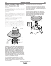
Put another rubber band on the base of the arm. Use
(2) 1.75” bolts with nuts to mount the arm (Fig. 6B) to
the hanging adapter (Fig. 6A), using both mounting
holes as shown in the inset of Figure 6.
AB
E
AB
E
20
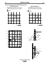
"#&##!
#&$#
(continued)
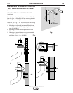
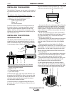
MOUNTING THE LFA 3.1 OR 4.1 ARM TO THE
WALL-MOUNTING BRACKET
Leave the tape and plastic packaging on the extrac-
tion arm sections until the arm is completely installed
(including mounting the hood). The arm is spring-bal-
anced to compensate for the weight of the hood and
will spring out quickly if it is not mounted securely,
with the hood in place.
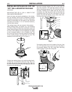
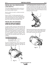
The rotating hinge of the arm comes in three pieces:
Metal rotating hinge, red plastic ring, and clamping
pin. Refer to Figure 3. Mount the red plastic ring to the
metal rotating hinge by fitting the clamping pin through
the hole in the rotating rod, and snapping it into place
on the U-shaped indents on the red plastic ring. The
lip of the ring should fit securely against the top edge
of the rotating flange, yet rotate with the rod. The
assembly should look like Part C in Figure 4.
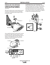
Position the rotating hinge on the wall mounting brack-
et (See Fig. 4) so that the cable hole (Fig. 4A) is on
the wall side and the long side of the pin (Fig. 4B) is in
the front. Use the four 3” bolts with washers and nuts
to secure the rotating hinge.
A
B
D
E
F
C
A
B
D
E
F
C
20
D
E
C
B
A
D
E
C
B
A
20
2
1
3
2
1
3
20