


"##
""##!(
"###
#$##
"#!#"#!""!
(continued)
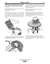
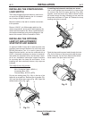
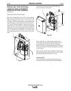
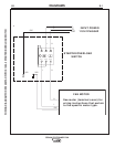
INSTALLING THE CONTROL BOX
Mount the Thermal Relay (Fig. 27A) to the Contactor
(Fig. 27D) by snapping the pin on the bottom of the
Thermal Relay into the hole in the top of the
Contactor. The three shorting pins at the bottom of the
Thermal Relay should connect into terminals 2T1,
4T2, and 6T3 of the Contactor. Tighten the screw con-
nections at 2T1, 4T2, and 6T3, and have a qualified
electrician make the remaining connections inside the
Control Box per the wiring diagram in the back of this
manual. (NOTE the orientation of the control box
when referencing Figures 27, 28, and the wiring dia-
gram).
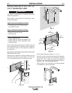
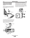
Mount the connection box to the wall using four
screws as shown in Figure 28.
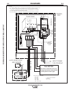
Feed a 120VAC, 1ph, 60Hz supply cable into the
Control Box. Route a power cable out of the box, to
the terminal box on the motor of the SF2400 fan.
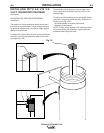
Route the 36 ft. connection cable into the Control Box.
Connect all cables per the wiring diagram in the back
of this manual.
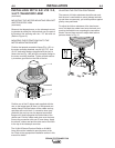
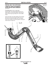
Make sure the thermal relay is always in manual oper-
ation by setting the blue button (Fig. 27C) at H. Check
also that the thermal relay is set to 10.0A.
"#
It is not necessary to use the K1669-2 Lamp Kit in
conjunction with a K1494-2 Starter/Overload Switch.
A
BC
D
A
BC
D
20
T
Y
P
E
T
Y
P
E
S
E
R
.
N
R
.
S
E
R
.
N
R
.
W
.
W
.
A
L
K
M
A
A
R
-
H
O
L
L
A
N
D
A
L
K
M
A
A
R
-
H
O
L
L
A
N
D
A
DBC
C
T
Y
P
E
T
Y
P
E
S
E
R
.
N
R
.
S
E
R
.
N
R
.
W
.
W
.
A
L
K
M
A
A
R
-
H
O
L
L
A
N
D
A
L
K
M
A
A
R
-
H
O
L
L
A
N
D
A
D BC
C
20