


"##
""##!(
"# &# #
##"!
(continued)
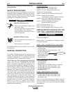
MOUNTING THE MOTOR-MOUNTING BRACKET
AND TELESCOPIC ARM
(continued)
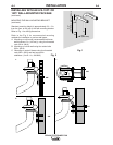
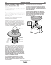
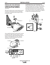
Remount the telescopic arm on the telescopic mount-
ing bracket by sliding the friction block over the post of
the bracket and securing with the 1.75” bolt and nut
(Refer to Figure 10).
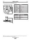
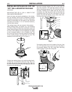
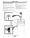
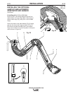
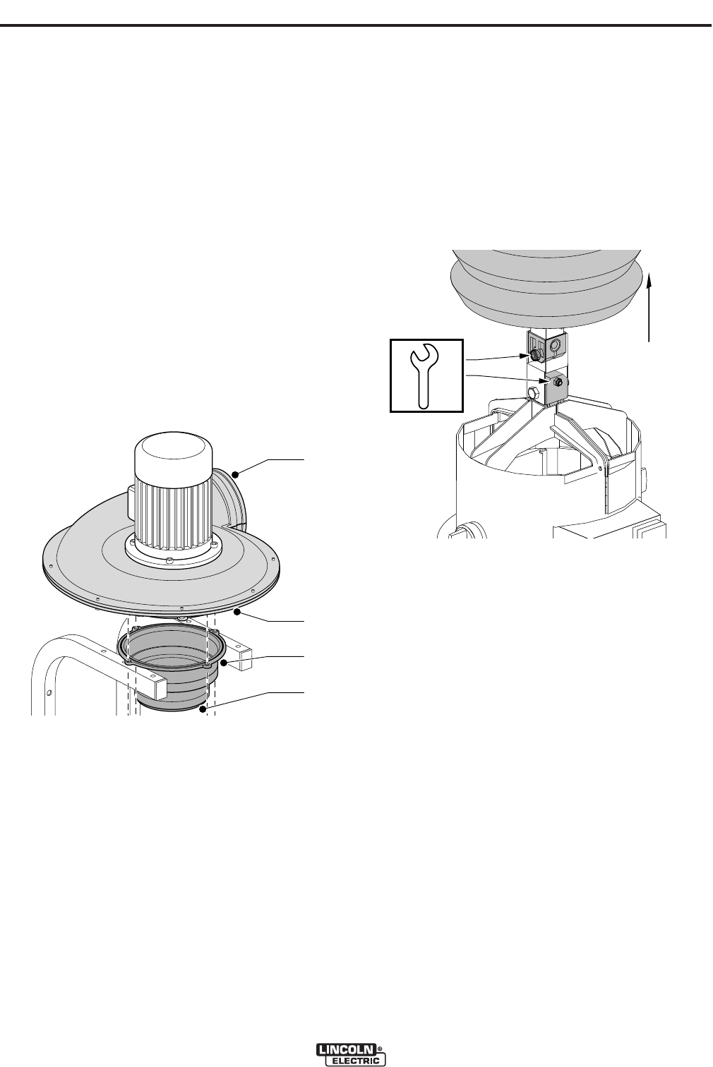
MOUNTING THE EXTRACTION FAN TO THE
MOTOR MOUNTING BRACKET
Position the tapered connection flange (Fig. 14C) on
the motor mounting brackets; use the (2) 0.75” and
(2) 2.5” bolts with washers (supplied with the fan) to
secure the fan (Fig. 14B) and the connection flange to
the motor mounting brackets. Tighten all bolts secure-
ly to make a good seal on the inlet of the fan.
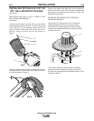
Position one of the 8” rubber seals supplied with the
arm on the largest part (8” diam.) of the tapered con-
nection flange. Roll the bottom of the rubber seal up,
and slide one end of the 4 ft. connection hose (sup-
plied with the arm) up over the tapered connection
flange until it butts up against the folded side of the
rubber seal. Fold the rubber seal down over the hose.
Secure the connection with one 8” hose clamp. Apply
the other 8” rubber seal and the other end of the hose
to the top of the telescopic arm tube.
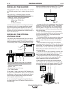
The K1494-2 Starter/Overload Switch or K1669-2
Lamp Kit must be installed to provide power to the
fan. Refer to the appropriate Installation section in this
manual for details.
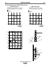
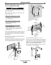
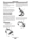
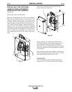
ADJUSTING THE FRICTION POSITIONING
The amount of friction resistance should be set such
that the arm is comfortable to move (always test both
up and down movements), yet hold its position against
gravity once positioned.
To adjust the friction resistance of the hood move-
ment, fold back the rubber band onto the hood, and
push up the flexible hose, exposing the connection
blocks. Use an 8mm wrench to adjust both bolt/nut
pairs as shown in Fig. 15.
A
B
D
C
C
A
B
D
C
C
20
B
B
B
C
B
B
B
C
20