


"##
""##!(
"# &# #
##"!
The installer is responsible for following local safety
codes and regulations.
------------------------------------------------------------------------
Before drilling, verify locations of existing gas, water,
or electrical conduits.
------------------------------------------------------------------------
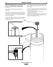
K1655-3 LTA 2.0 Telescopic Arm Includes
:
• Telescopic arm, assembled
• (1) Flexible hose, (2) 8” Rubber seals
for connection to fan
K1657-1 Wall Mounting Bracket Includes:
• (2) Bracket pieces
• Tapered Connection Flange
• 8” Hose Clamp
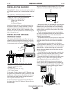
K1656-1 SF2400 Stationary Fan Includes:
• SF2400 Stationary Fan
• (2) Bolts, M8x1.25, 20mm long (about 0.75”)
• (2) Bolts, M8x1.25, 65mm long (about 2.50”)
• (4) Washers, M8
Note: K1494-2 Starter/Overload or K1669-2 Lamp Kit
must be installed with this package. See the appropri-
ate Installation section in this manual for details on
this equipment.
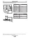
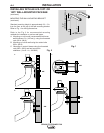
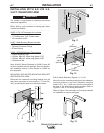
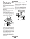
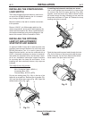
MOUNTING THE MOTOR-MOUNTING BRACKET
AND TELESCOPIC ARM
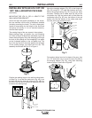
Disconnect the telescopic mounting bracket from the
arm before mounting, by removing the 1.75” bolt (Fig.
12C), and sliding the post out of the friction block.
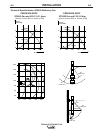
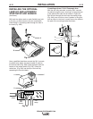
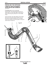
Drill (5) holes (Reference Figures 11, 12, 13).
Mount the motor mounting bracket and the telescopic
mounting bracket to the wall. Standard mounting
height is 5 ft., 3 in. (1300 mm) from the work table to
the post of the telescopic mounting bracket. Refer to
Figures 11 and 12 for drilling dimensions.
Refer to Figure 2 for information on mounting methods
for installation on various wall types.
&!
4.7"
(120 mm)
10"
(255 mm)
9"
(230 mm)
0.4"
(10 mm)
8.3"
(210 mm)
ø0.5"
(ø13 mm)
C
4.7"
(120 mm)
10"
(255 mm)
9"
(230 mm)
0.4"
(10 mm)
8.3"
(210 mm)
ø0.5"
(ø13 mm)
C
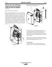
20
9" (230 mm)
8.3"
(210 mm)
6.3" (160 mm)
9" (230 mm)
8.3"
(210 mm)
6.3" (160 mm)
20
CB
A
C
C B
A
C
20
20