


A-3
INSTALLATION
POWER WAVE® 655/R
A-3
INPUT CONNECTION
Only a qualified electrician should connect the
input leads to the Power Wave®. Connections
should be made in accordance with all local and
national electrical codes and the connection dia-
gram located on the inside of the reconnect/input
access door of the machine. Failure to do so may
result in bodily injury or death.
-------------------------------------------------------------
Use a three-phase supply line. A 1.75 inch (45 mm)
diameter access hole for the input supply is located on
the upper left case back next to the input access door.
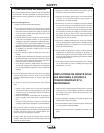
Connect L1, L2, L3 and ground according to the Input
Supply Connection Diagram decal located on the
inside of the input access door or refer to Figure A.1 .
INPUT FUSE AND SUPPLY WIRE
CONSIDERATIONS
Refer to the Technical Specifications at the beginning
of this Installation section for recommended fuse and
wire sizes. Fuse the input circuit with the recommend-
ed super lag fuse or delay type breakers (also called
“inverse time” or “thermal/magnetic” circuit breakers).
Choose an input and grounding wire size according to
local or national electrical codes. Using fuses or circuit
breakers smaller than recommended may result in
“nuisance” shut-offs from welder inrush currents, even
if the machine is not being used at high currents.
INPUT VOLTAGE CHANGE OVER
(FOR MULTIPLE INPUT VOLTAGE
MACHINES ONLY)
Welders are shipped connected for the highest input
voltage listed on the rating plate. To move this con-
nection to a different input voltage, see the diagram
located on the inside of the input access door. If the
main reconnect switch or link position is placed in the
wrong position, the welder will not produce output
power.
If the Auxiliary (A) lead is placed in the wrong position,
there are two possible results. If the lead is placed in a
position higher than the applied line voltage, the
welder may not come on at all. If the Auxiliary (A) lead
is placed in a position lower than the applied line volt-
age, the welder will not come on, and the two circuit
breakers in the reconnect area will open. If this
occurs, turn off the input voltage, properly connect the
(A) lead, reset the breakers, and try again.
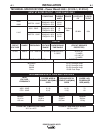
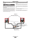
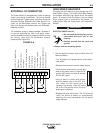
FIGURE A.1 - CONNECTION DIAGRAM ON CONNECTION/INPUT ACCESS DOOR
W / L3
V
/ L2
U / L1
THE LINCOLN ELECTRIC CO. CLEVELAND, OHIO U.S.A.
XA
S24190
use or service this equipment.
Do not touch electrically live parts.
removed.
Only qualified persons should install,
Do not operate with covers
inspecting or servicing machine.
Disconnect input power before
.
.
.
.
CR1
INPUT SUPPLY CONNECTION DIAGRAM
NOTE: Turn main input power to the machine OFF before performing connection procedure. Failure to
do so will result in damage to the machine.
WARNING